Version 06 teledynedalsa.com/ipd 12
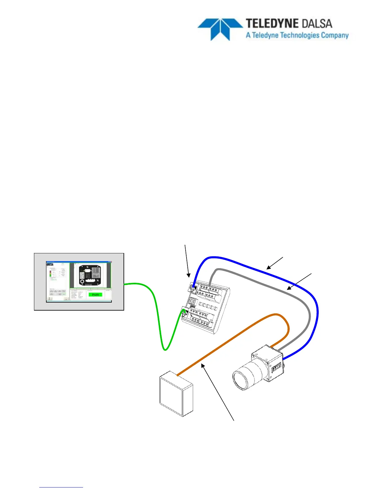
Ethernet and I/O Setup with Lamp
1.
Connect the M12-8 male end of the Ethernet cordset
(A-BVS-E8S-X) to the M12-8
female connector labeled “LAN”
on the camera.
2.
Connect the RJ45 end of the Ethernet cordset
to the RJ45 connector labeled
“CAM LAN”
on the Panel Link breakout module (A-BVS-PL-100)
3.
Connect the RJ45 labeled “LAN”
on the breakout module to the controlling PC,
PLC or the factory LAN
4.
Connect camera PWR, GND and I/O from the control panel to the breakout screw
terminals.
5.
Connect the M12-8 male end of the IO-PWR cordset
(A-BVS-IO8S-X) to the M12-
8 female connector on the camera labeled “I/O PWR”
6.
Connect the open-ended wires of the IO-PWR cordset
to their respective
connections on the breakout module.
BOA System
A-BVS-E8S-X
A-BVS-PL-100
Setup Computer, PLC
or Factory Network
Cat5 Cable
A-BVS-IO8S-X
LED Lamp
A-BVS-L5S-X