Version 06 teledynedalsa.com/ipd 24
Serial Port Connection
The RS-232 serial port is accessible through the Lamp connector. By default, the serial
port settings are set as follows:
Port definition Setting
Baud Rate 115200
Data Bits 8
Parity None
Stop Bits 1
Flow Control None
RS-232 Hardware Configuration
These port settings can be changed through the GUI by configuring the “RS232 Stream
Settings”
in the Setup Control panel. Refer to the iNspect
Express user manual for
details.
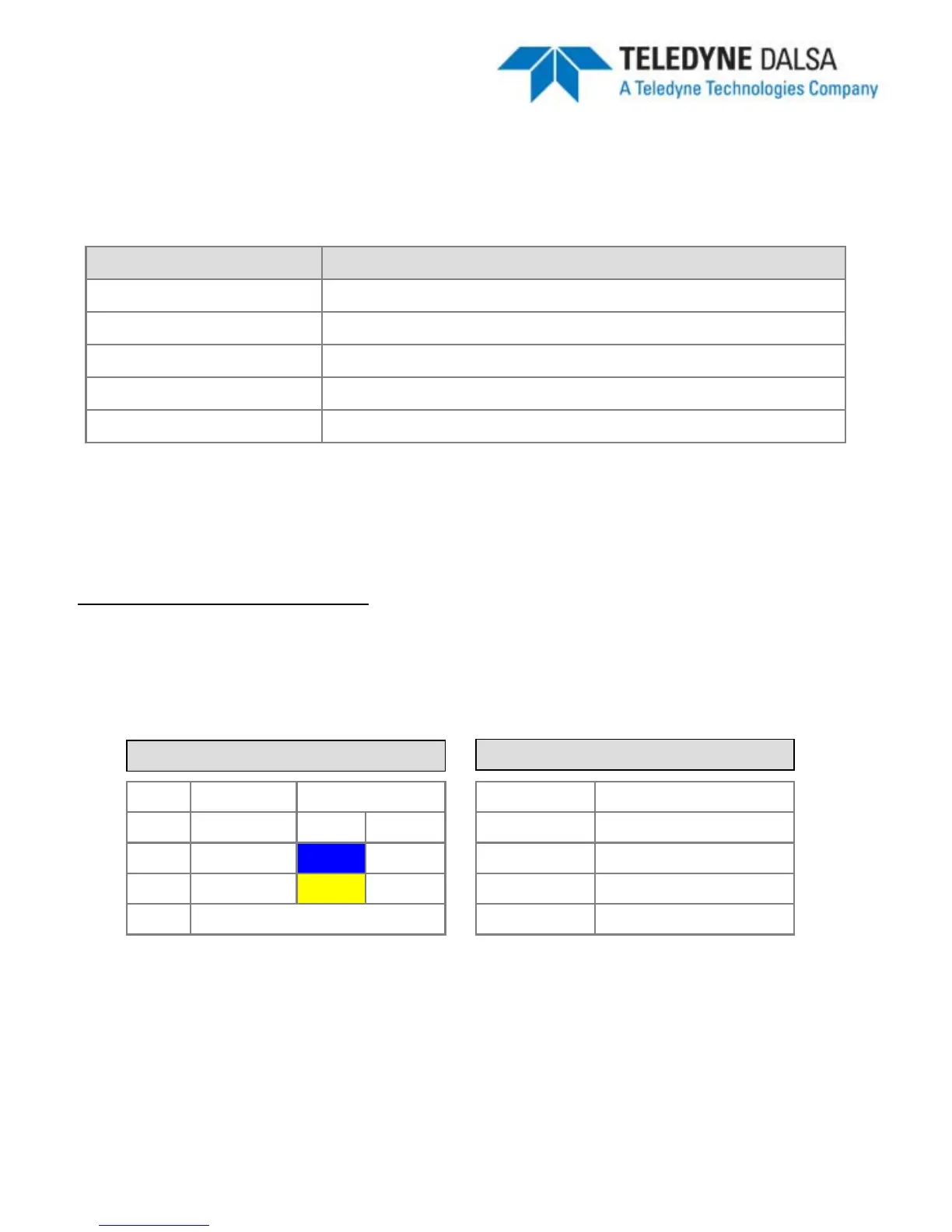
BOA LAMP M12-5 Connector
Pin Name Color
2 RS232 RX
White
3 GND
Blue
5 RS232 TX
Yellow
1,4
Not required
Electrically, three (3) signals are required to make a serial port connection between
BOA and another device as shown below. RS232 is a “point-to-point”
connection, so
the Receive and Transmit lines must be crossed in the cable.
3
rd
Party DSUB-9 Connector
Pin Name
3 TX
5 GND
2 RX
1,4,6,7,8,9 Not required
Note: It is important to establish a common ground between BOA and the connecting
3
rd
party device.