20 Piranha2 User’s Manual
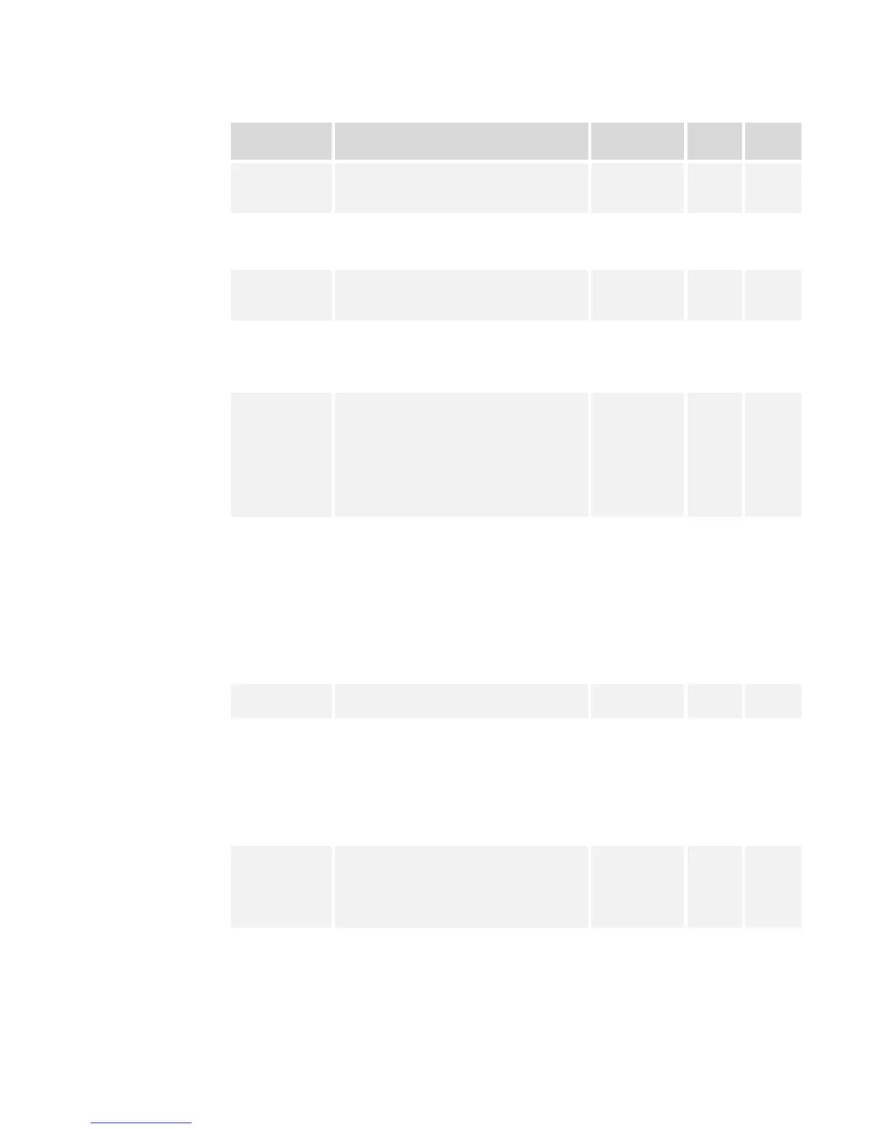
Table 6: Piranha2 40MHz Timing (Fixed Integration Mode)
Symbol Definition Min (ns) Typ
(ns)
Max
(ns)
twSYNC The minimum low width of the EXSYNC
pulse when not in SMART EXSYNC
mode.
100
twSYNC
(SMART)
*
The minimum low width of the EXSYNC
pulse when in SMART EXSYNC modes to
guarantee the photosites are reset.
2,000
twSYNC_INT The minimum width of the high pulse
when the “SMART EXSYNC” feature is
turned off
100
twSYNC_INT
(SMART)
*
Is the integration time when the “SMART
EXSYNC” feature is available and turned
on. Note that the minimum time is
necessary to guarantee proper operation.
2,000
tLINE PERIOD
(t
LP
)
The minimum and maximum line times
made up of tTransfer, tREADOUT plus
tOVERHEAD to meet specifications.
53,190 (8K4T)
106,382 (8K2T)
40,485 (6K4T)
80,645 (6K2T)
27,624 (4K4T)
54,054 (4K2T)
28,248 (2K2T)
15,313 (1K2T)
10
6
tTransfer The time from the reception of the falling
edge of EXSYNC to the rising edge of
LVAL when pretrigger is set to zero.
Pretrigger reduces the number of clocks to
the rising edge of LVAL but doesn’t
change the time to the first valid pixel. If
the fixed integration time mode of
operation is available and selected then
the integration time is added to the
specified value.
1,420 +/-50
twFixed Int. Fixed Integration Time mode of operation
for variable exsync frequency.
800 t
LP
–
2,000
tREADOUT Is the number of pixels per tap times the
readout clock period. Pretrigger = 0.
51,200 (8K4T)
102,400 (8K2T)
38,400 (6K4T)
76,800 (6K2T)
25, 600 (4K4T)
51,200 (4K2T)
25,600 (2K2T)
12,800 (1K2T)
tOVERHEAD Is the number of pixels that must elapse
after the falling edge of LVAL before the
EXSYNC signal can be asserted. This time
is used to clamp the internal analog
electronics
540+/-50
thPR Applies when the PRIN exposure control
feature is enabled . The PRIN signal must
be held a minimum time after the
EXSYNC falling edge to avoid losing the
integrated charge
0
03-32-00493-11 DALSA