14 Piranha2 User’s Manual
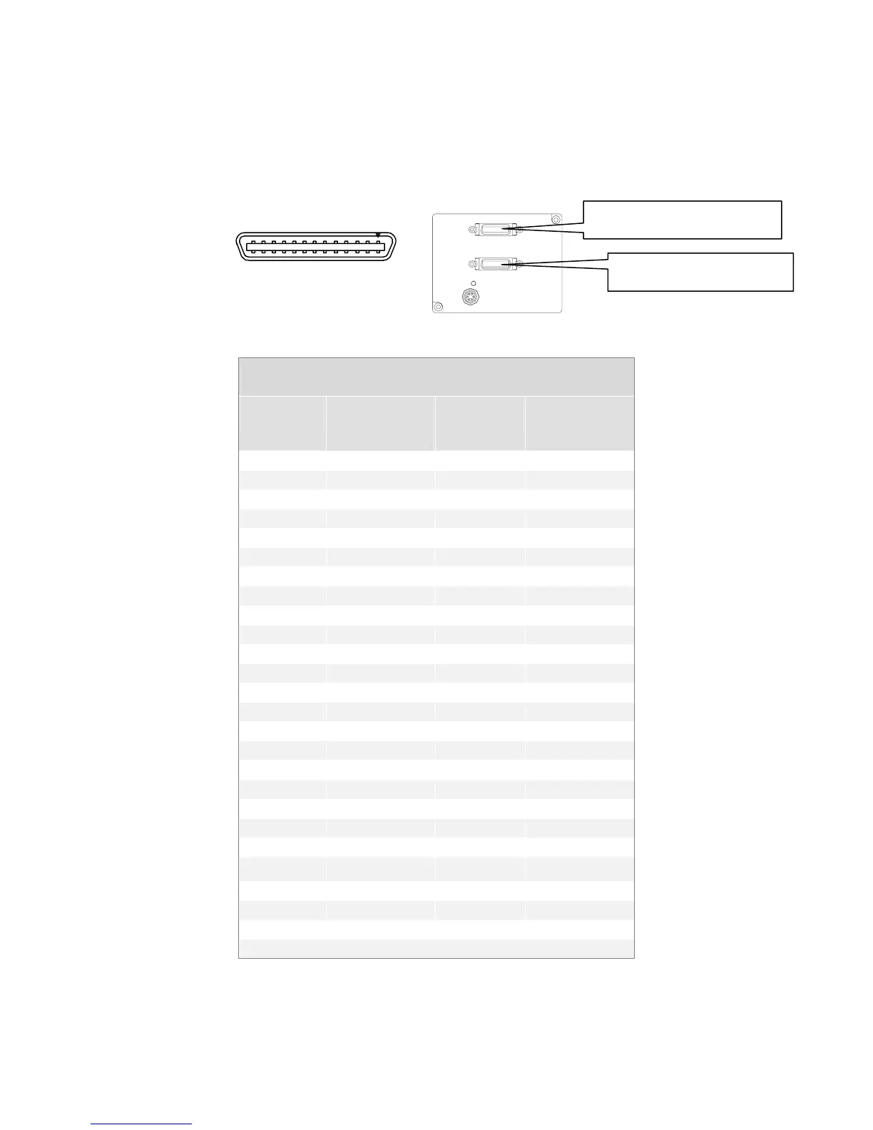
2.3 Connectors, Pinouts, and Cables
The camera uses a high-density 26-pin MDR26 connector for Camera Link control signals,
data signals, and serial communications, and a 6-pin Hirose connector for power.
MDR26 Female
1
14
13
26
Mating Part
: 3M 334-31 series
Cable:
3M 14X 26-SZLB-X X X-0LC
**
Base, Medium, and Full Configuration
Medium and Full Configuration Only
Table 3: Camera Link Medium and Full Configuration
Medium and Full Configurations
Up to an additional 2 Channel Link Chips
Camera
Connector
Right Angle
Frame
Grabber
Channel
Link Signal
Cable Name
1 1 inner shield Inner Shield
14 14 inner shield Inner Shield
2 25 Y0- PAIR1-
15 12 Y0+ PAIR1+
3 24 Y1- PAIR2-
16 11 Y1+ PAIR2+
4 23 Y2- PAIR3-
17 10 Y2+ PAIR3+
5 22 Yclk- PAIR4-
18 9 Yclk+ PAIR4+
6 21 Y3- PAIR5-
19 8 Y3+ PAIR5+
7 20 100 ohm PAIR6+
20 7 terminated PAIR6-
8 19 Z0- PAIR7-
21 6 Z0+ PAIR7+
9 18 Z1- PAIR8-
22 5 Z1+ PAIR8+
10 17 Z2- PAIR9+
23 4 Z2+ PAIR9-
11 16 Zclk- PAIR10-
24 3 Zclk+ PAIR10+
12 15 Z3- PAIR11+
25 2 Z3+ PAIR11-
13 13 inner shield Inner Shield
26 26 inner shield Inner Shield
*Exterior Overshield is connected to the shells of the connectors on both ends.
**3M part 14X26-SZLB-XXX-0LC is a complete cable assembly, including connectors.
03-32-00493-11 DALSA