11 Spyder2 User’s Manual
03-032-10091-06 Teledyne DALSA
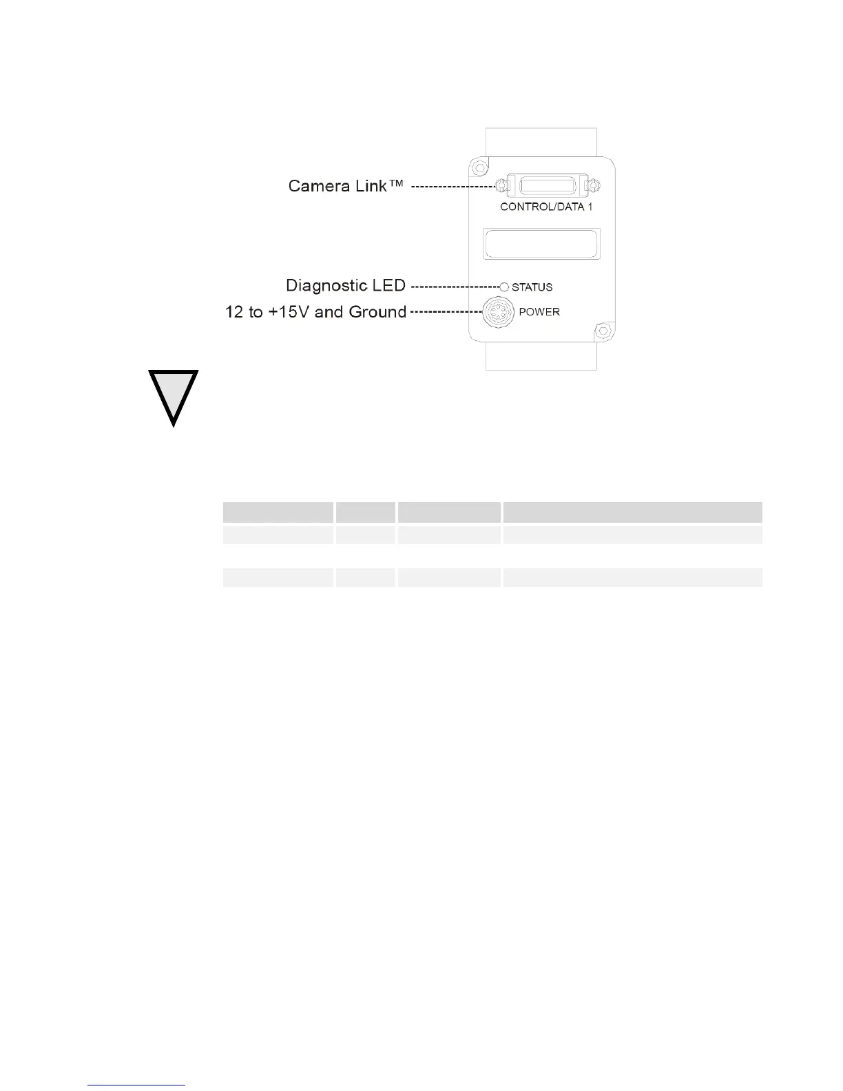
Figure 3: Camera Inputs / Outputs
WARNING:
It is extremely important that you apply the appropriate voltages to your camera.
Incorrect voltages will damage the camera. See section 2.2.3 Power Connector for details.
2.2.1 LED Status Indicator
Table 1: Status LED
LED state Priority Camera Status Condition
Blinking RED 1 Error Fatal hardw ar e fai lure
St ead y RED 2 Warning Monitoring task failure
Lengthy operation in progress
Steady GREEN 4 OK H ealthy
2.2.2 Camera Link Data Connector
The Camera Link i nter face is implemented as a Base Configuration in the Sp y d er 2
cameras. A Base Configuration uses 1 M DR26 connector and 1 Channel Link chip. The
main characteristics of the Base Configuration are:
• Ports supported: A, B, C
• Serializer bit width: 28
• Number of chips: 1
• Number of MDR26 connectors: 1