12 Spyder2 User’s Manual
03-032-10091-06 Teledyne DALSA
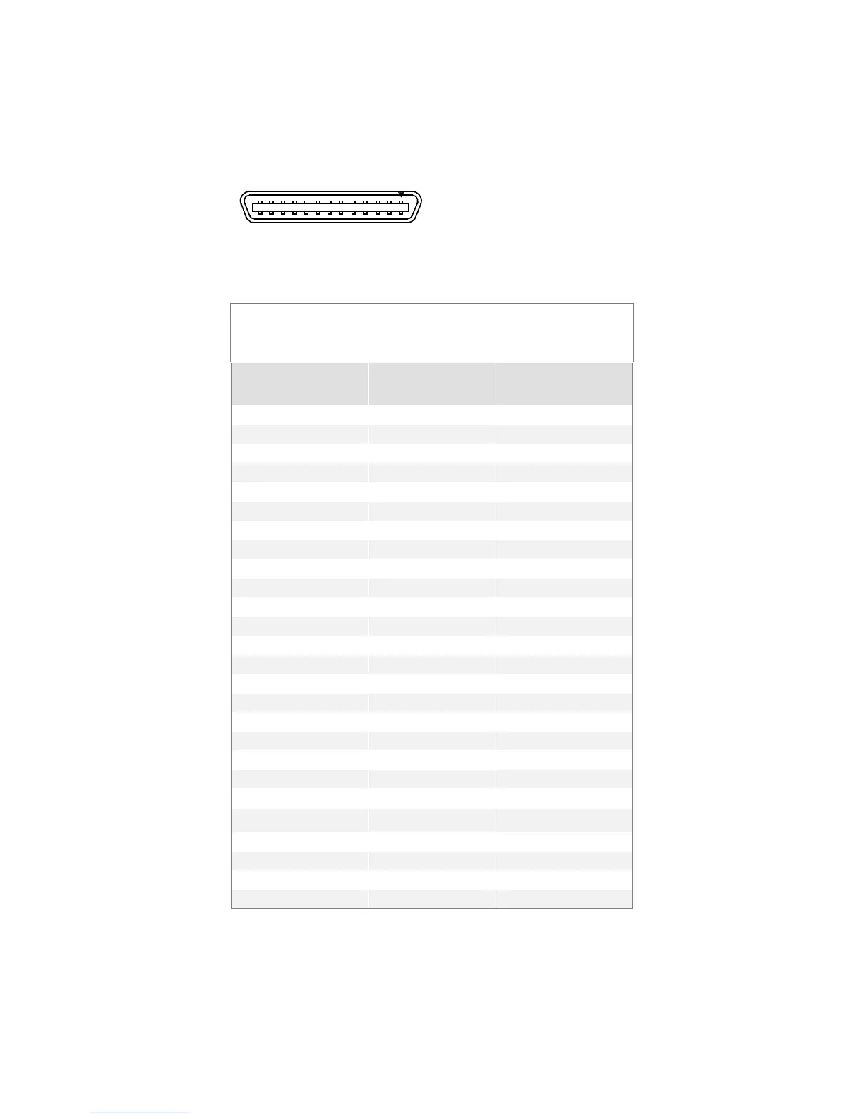
Data Connector
Figure 4: MDR26 Connector
MDR26 Female
1
14
13
26
Mating Part
: 3M 334-31 ser ies
Cable:
3M 14X26-SZLB-XXX-0LC
**
Table 2: Camera Link Base Configuration
Base Configuration
One Channel Link Chip + Camera Control +Serial
Communication
Camera Connector Right Angle Frame
Grabber
Channel Link Signal
14 14 Inner shield
15 12 X0+
16 11 X1+
17 10 X2+
5 22 Xclk-
6 21 X3-
7 20 Ser T C+
8 19 Ser T FG-
9 18 CC1-
22 5 CC1+
23 4 CC2-
24 3 CC3+
12 15 CC4+
13 13 Inner shield
26 26 Inner shield
Unused pairs should be terminated in 100 ohms at both ends of the cable.