11
180R9265 / IOM APP 16-22 Appendices - v02 / 01.2013
Data sheet APP 16-22
13. Installation 13.1 Mounting
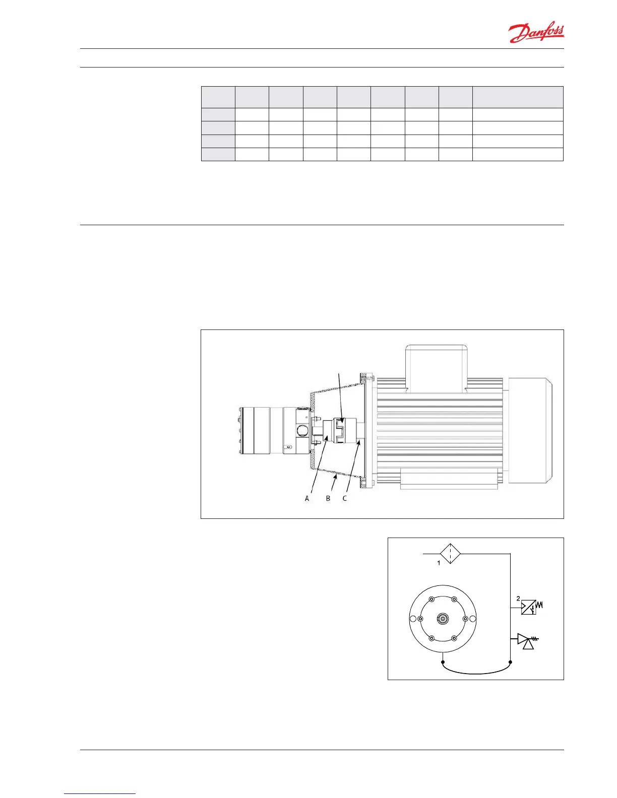
The gure below illustrates how to mount the
pump and connect it to the electric motor/
combustion engine.
If alternative mounting is required, please
contact Danfoss RO Sales Organization for
further information.
To ensure easy mounting of the exible coupling
without using tools, the tolerances must be
dimensioned accordingly.
Note: Any axial and radial loads on the pump
shaft must be avoided.
Pump A (mm)
(P)
B (mm)
(HD)
C (mm)
(H)
D (mm)
(A)
E (mm)
(B)
F (mm)
(LB)
G (mm) IEC Electric motor
APP 16 450 560 225 356 286 675 262 37 kW, IEC 225 S4
APP 17 450 560 225 356 311 705 262 45 kW, IEC 225 M4
APP 19 550 615 250 406 349 775 265 55 kW, IEC 250 M4
APP 22 550 680 280 457 368 835 265 75 kW, IEC 280 S4
Note: Examples of dierent pump/motor sizes
and drawing dimensions are only for IEC
motors and couplings. Please always check
required motor power and dimensions.
13.2 Open-ended system with direct water
supply
In order to eliminate the risk of cavitation, a
positive inlet pressure is always to be maintained.
Please see technical data (section 3.) for specic
pressure values.
1. Place the lter (1) in the water supply line in
front of the pump.
2. Place a monitoring pressure switch (2) - set
at min. inlet pressure - between lter and
pump inlet.
The monitoring switch must stop the pump
at pressures lower than min. inlet pressure.
Please see technical data (section 3.) for
specic pressure values
3. Install a low pressure safety valve or a
pressure relief valve (3) in order to avoid
system or pump damage in case the pump
stops momentarilly or spinning backwards.
3
Note: If a non return valve is mounted in the
inlet line, a low pressure relief valve is also
required between non return valve and pump
as protection against high pressure peaks.
A: Flexible coupling
B: Bell housing
C: Motor shaft
Ensure 3-5 mm (0.12-0.2 inches) air gap
between coupling parts.

 Loading...


