Application 17, Type 2 Only
EI.65.D4.02
110
6.3.18 Application 17, Type 2 Only
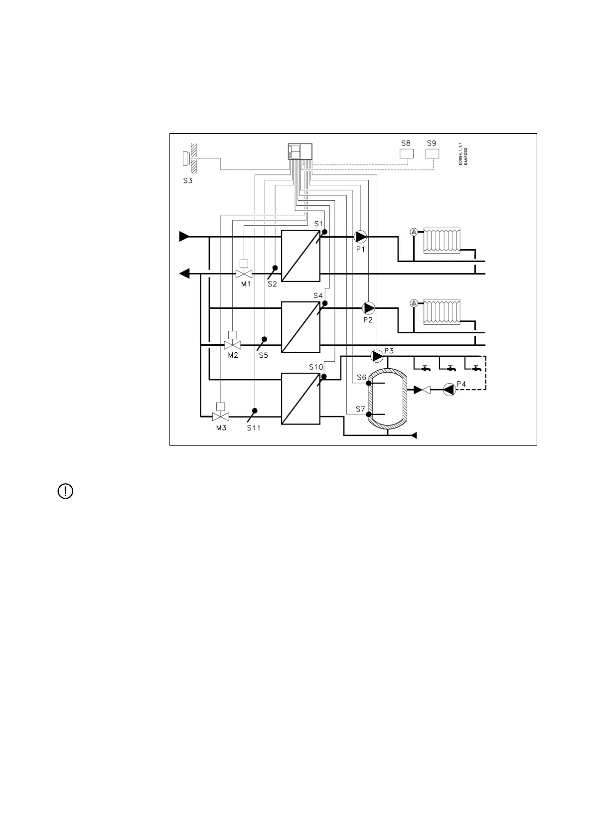
System diagram 17A
Two separate heat circuits. Hot-water circuit with indirect control of storage tank.
Note:
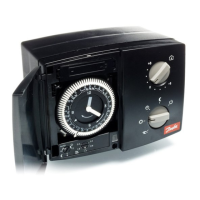
ECL 2000 Type 2 must be used to control this application.
Heat circuit 1 The motor valve M1 controls the flow temperature, which is measured by the sen-
sor S1. The return temperature measured by the sensor S2 can be limited. The cir-
culation pump P1 is running when the reference flow temperature is above 20 °C
or the outdoor temperature is below 2 °C.
Heat circuit 2 The motor valve M2 controls the flow temperature, which is measured by the sen-
sor S4. The return temperature measured by the sensor S5 can be limited. The cir-
culation pump P2 is running when the reference flow temperature is above 20 °C
or the outdoor temperature is below 2 °C.
Hot-water circuit The motor valve M3 controls the charging temperature, which is measured by the
sensor S10. The upper and lower storage tank temperatures are measured by the
sensors S6 and S7, respectively. A low S6 temperature causes the charging pump
P3 to start and the pump is stopped when a high temperature is measured at S7. It
is possible to limit the return temperature measured by S11. The pump P4 main-
tains circulation through the storage tank but is not controlled by the ECL 2000.