Electrical Connections
EI.65.D4.02
18
4.5 EIA 232 Connection
The ECL 2000 is equipped with two EIA 232 connectors, one on the front panel
and one on the rear panel.
When the ECL 2000 is delivered, the front panel EIA 232 connector is protected
by a small cover plate. This cover plate should be left in place when the connector
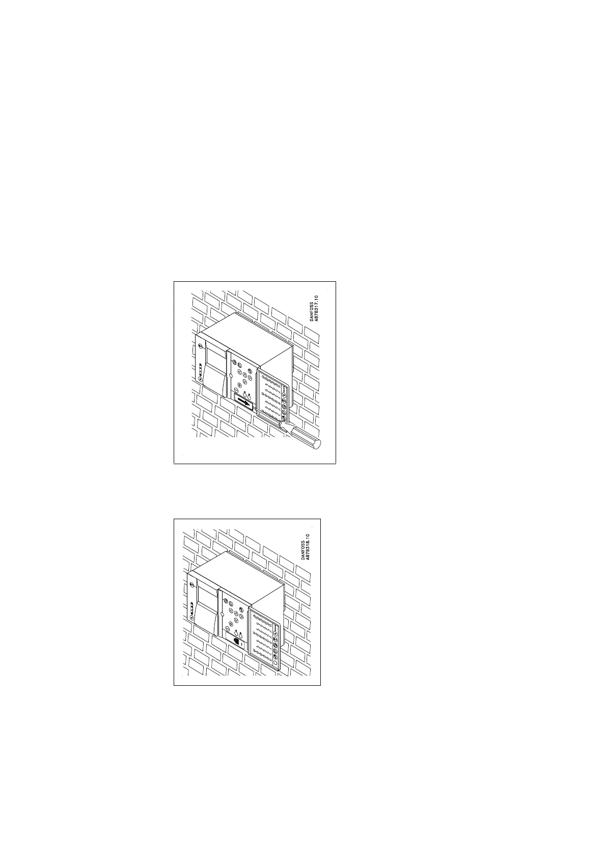
is not being used. Figure 16 shows how it can be removed:
1. Carefully lift the right-hand side of the cover plate with the tip of a screw-
driver, at the same time sliding the cover plate to the right, as indicated by
the arrow.
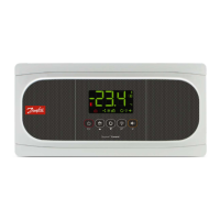
Figure 16. Removing the cover plate from the EIA 232 connector
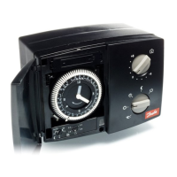
Figure 17 shows the front panel connector after the cover plate has been removed.
Figure 17. The front panel EIA 232 connector
The location of the rear panel EIA 232 connector is shown in Figure 11 on
page 13, in Figure 12, page 14 and in Figure 13, page 15.