Application 9
EI.65.D4.02
75
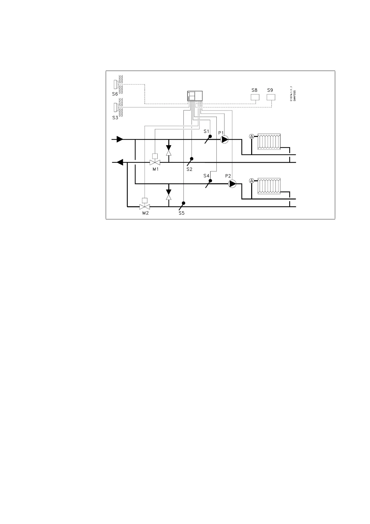
System diagram 9B
Two separate heat circuits, with direct connection to the district heating network
and mixing via by-pass valve.
Heat circuit 1 The motor valve M1 controls the flow temperature, which is measured by the sen-
sor S1. The return temperature measured by the sensor S2 can be limited. The cir-
culation pump P1 is running when the reference flow temperature is above 20 °C
or the outdoor temperature is below 2 °C.
Heat circuit 2 The motor valve M2 controls the flow temperature, which is measured by the sen-
sor S4. The return temperature measured by the sensor S5 can be limited. The cir-
culation pump P2 is running when the reference flow temperature is above 20 °C
or the outdoor temperature is below 2 °C.
 Loading...