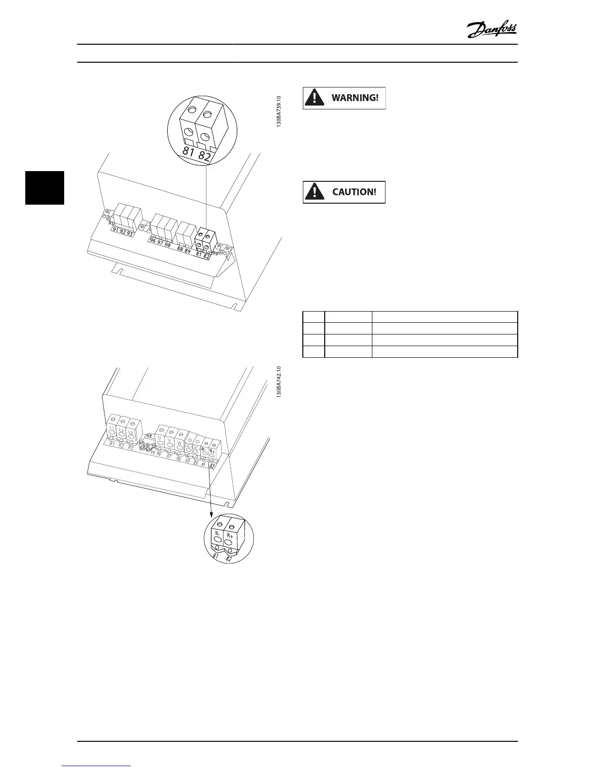
Illustration 4.26: Brake connection terminal for C3.
Illustration 4.27: Brake connection terminal for C4.
If a short circuit in the brake IGBT occurs, prevent power
dissipation in the brake resistor by using a mains switch
or contactor to disconnect the mains for the frequency
converter. Only the frequency converter shall control
the contactor.
Place the brake resistor in an environment free of fire
risk and ensure that no external objects can fall into the
brake resistor through ventilation slots.
Do not cover ventilation slots and grids.
4.1.22 Relay Connection
To set relay output, see par. group 5-4* Relays.
No. 01 - 02 make (normally open)
01 - 03 break (normally closed)
04 - 05 make (normally open)
04 - 06 break (normally closed)
Electrical Installation
VLT
®
HVAC Drive Operating Instructions
38 MG.11.AD.02 - VLT
®
is a registered Danfoss trademark
4