4.1.24 Access to Control Terminals
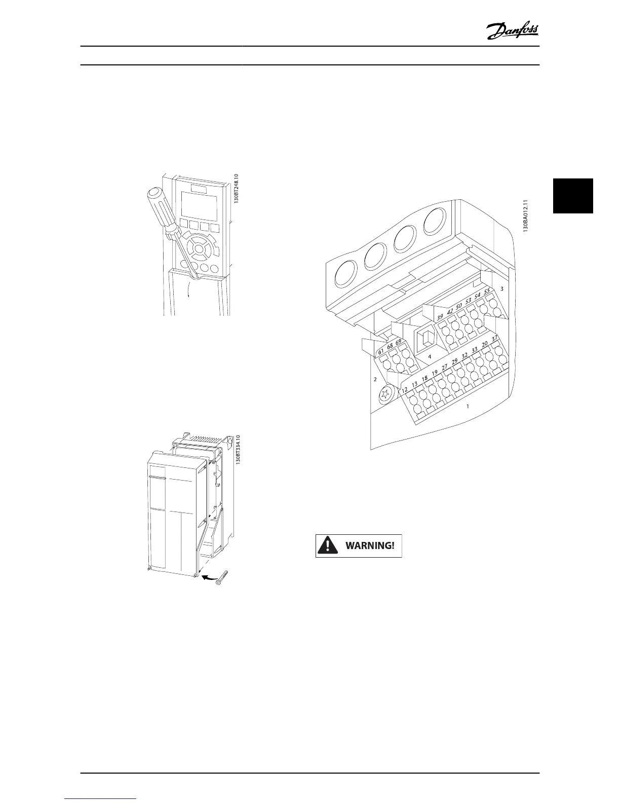
All terminals to the control cables are located underneath the
terminal cover on the front of the frequency converter.
Remove the terminal cover with a screwdriver.
Illustration 4.32: Access to control terminals for A2, A3, B3,
B4, C3 and C4 enclosures
Remove front-cover to access control terminals. When replac-
ing the front-cover, please ensure proper fastening by
applying a torque of 2 Nm.
Illustration 4.33: Access to control terminals for A4, A5, B1,
B2, C1 and C2 enclosures
4.1.25 Control Terminals
Drawing reference numbers:
1. 10-pole plug digital I/O.
2. 3-pole plug RS-485 Bus.
3. 6-pole analog I/O.
4. USB connection.
Illustration 4.34: Control terminals (all enclosures)
4.1.26 How to Test Motor and Direction of
Rotation
Note that unintended motor start can occur, ensure no
personnel or equipment is in danger!
Please follow these steps to test the motor connection and
direction of rotation. Start with no power to the unit.
Electrical Installation
VLT
®
HVAC Drive Operating Instructions
MG.11.AD.02 - VLT
®
is a registered Danfoss trademark 41
4

 Loading...


