7
VIFZL35X © Danfoss 04/2011
Installation Guide Danfoss Link™ HC
GB
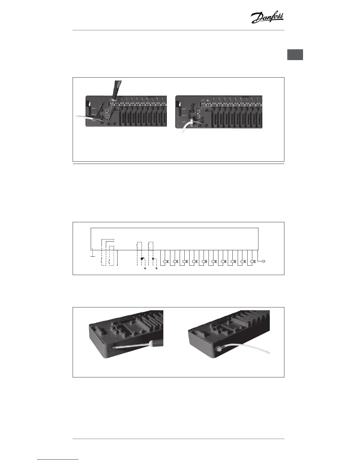
4: Connections for Heating & Cooling
When the system is in cooling mode the actuator output will be activated (ON for NC
actuators / OFF for NO actuators) when the temperature in a room exceeds the set point.
When the system is in cooling mode an independent dew-point alarm function should be installed.
1. Connect an external ON/OFF switch to the
terminals for Heating & Cooling. When this
switch is closed (ON) the system will switch
from heating to cooling.
2. Fix the cable.
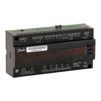
5: Power supply
When all actuators, pump and boiler controls and other inputs are installed, connect
the supply plug to a 230 V power supply.
If the power supply plug is removed during installation, make sure that the connection is made ac-
cording to existing law/legislation.
6: Wiring diagram
L
N
9 10876 54321
Actuator outputsRelays
Input
230 V~
50 Hz
External
antenna
L
N
Away
Heating / Cooling
max. 3 m
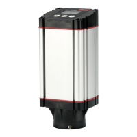
7: External antenne
The external antenna is installed as diverter when there is no transmission possible through a large
building, heavy construction or metal barrier, e.g. if the Danfoss Link™ HC is located in a metal cabinet/
box
1. Remove the plastic cover from the antenna con-
nection.
2. Connect the external antenna and place it on the
other side of the transmission barrier.
Connections