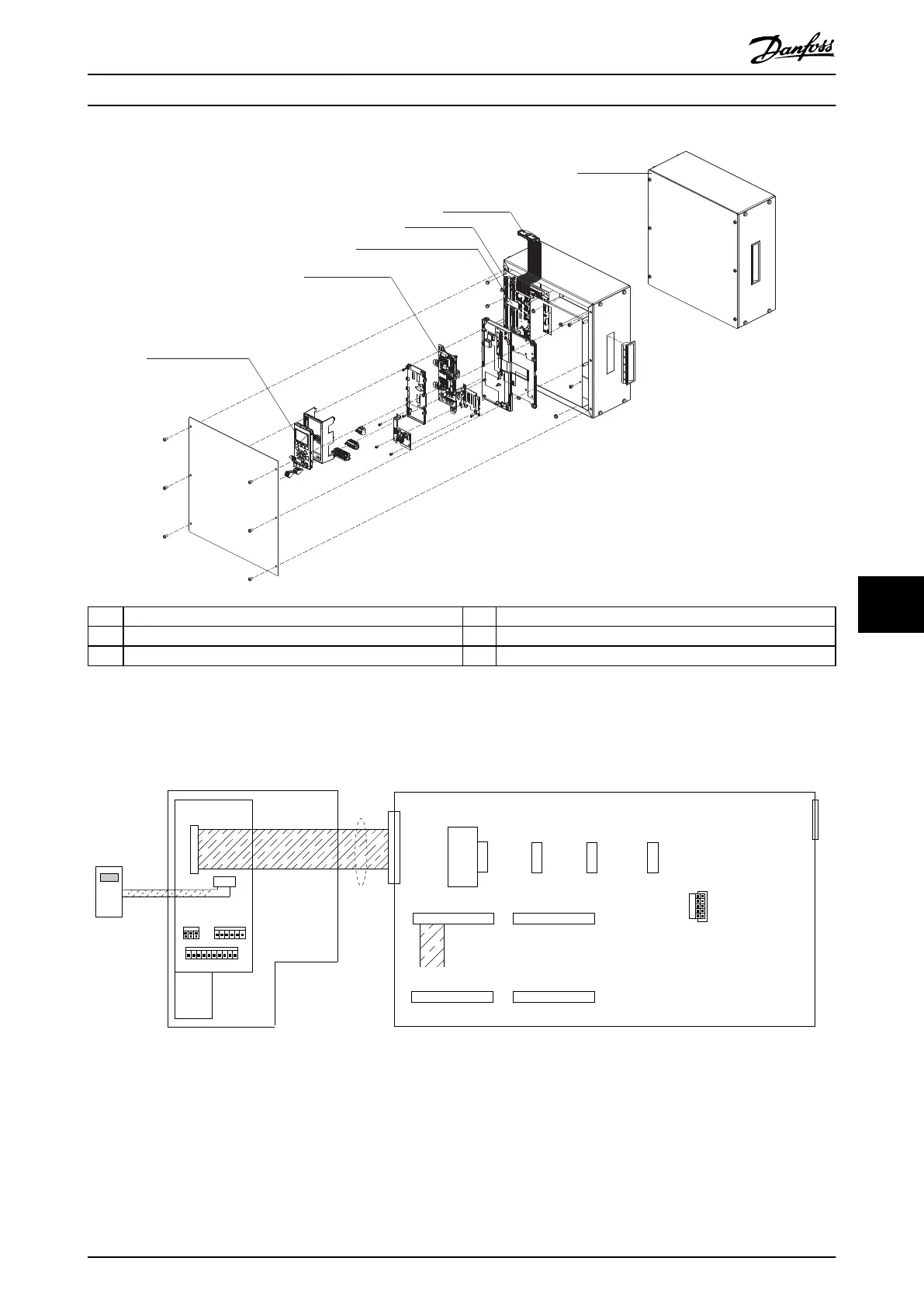
1 LCP 4 MDCIC
2 Control card 5 Cable connector (test kit to drive module)
3 Current scaling card 6 Assembled service kit
Illustration 9.4 Parallel Module Service Kit
CBL511
LCP
FC - X02
MK110
MK107
MK108
MK109
MK110
MK111
FK100
FK101
ANALOG I/O
DIGITAL INPUTS
MK112 MK114
MK113
TO DRIVE
MODULE
43
4344
1
442
431
442
431
442
442
431
MDCIC
130BE7855
Multi-Drive Control Interface Card
SLOT FOR
24 V DC
BACKUP
1 2
43 44
CURRENT
SCALING
CARD
INV1
130BF083.10
12
MK106
Illustration 9.5 Service Kit Internal Connection Diagram
Because the control card and current scaling card are not located within the individual module, but are on the control shelf,
the module cannot run without being connected to the service kit. The service kit includes an MDCIC and other
components required to run an individual drive module outside of the parallel drive system.
Special Test Equipment Service Guide
MG94A502 Danfoss A/S © 02/2019 All rights reserved. 123
9 9
 Loading...


