7.3.2 EMI Signal and Power Wiring
The following is an overview of general signal and power
wiring considerations related to electromagnetic compati-
bility (EMC) for typical commercial and industrial
equipment. Only certain high frequency phenomena (such
as RF emissions, RF immunity) are discussed. Low-
frequency phenomena (such as harmonics, mains voltage
imbalance, notching) are not covered. Special installations
or compliance to the European CE EMC directives requires
strict adherence to relevant standards and are not
discussed here.
Power wiring considerations for optional busbar kits used
in parallel drive systems are not discussed here. See the
Busbar Kit Instructions for more information about power
wiring.
7.3.3 Sources of EMI
D-sized and E-sized drives (Illustration 7.1) use IGBTs to
create the pulse-width modulated (PWM) output waveform
necessary for accurate motor control. These IGBTs rapidly
switch the xed DC bus voltage creating a variable
frequency and a variable voltage PWM waveform. This high
rate of voltage change [dU/dt] is the primary source of
generated EMI of the drives.
The high rate of voltage change caused by the IGBT
switching creates high-frequency EMI.
130BF931.10
L1
L2
L3
4
T1
T2
T3
1 2 3
5
6
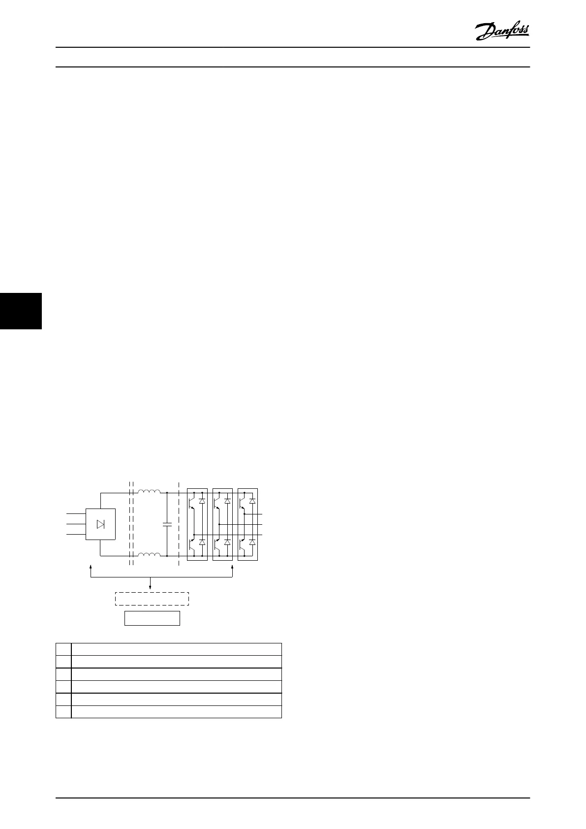
1 Rectier (SCR/diodes)
2 DC link (DC bus)
3 Inverter (IGBTs)
4 Power section
5 Logic-to-power interface
6 Control logic
Illustration 7.1 6-pulse Functionality Diagram
7.3.4 EMI Propagation
Drive-generated EMI is both conducted to the mains and
radiated to nearby conductors. Refer to Illustration 7.2.
Stray capacitance between the motor conductors,
equipment ground, and other nearby conductors results in
induced high-frequency currents.
High ground circuit impedance at high frequencies results
in an instant voltage at points reputed to be at ground
potential. This voltage appears throughout a system as a
common mode signal that interferes with control signals.
Theoretically, these currents return to the DC bus via the
ground circuit and a high-frequency (HF) bypass network
within the drive itself. However, imperfections in the drive
grounding or the equipment ground system can cause
some of the currents to travel out to the power network.
Unprotected or poorly routed signal conductors located
close to or in parallel to motor and mains conductors are
susceptible to EMI. Signal conductors are especially
vulnerable when they are run parallel to the power
conductors for any distance. EMI coupled into these
conductors can aect either the drive or the intercon-
nected control device. Refer to Illustration 7.4.
These currents tend to travel back to the drive. However,
imperfections in the system cause some current to ow in
undesirable paths and expose other locations to EMI.
When the mains conductors are close to the motor cables,
high-frequency currents can be coupled into the mains
supply.
Drive and Motor Application...
VLT
®
FC Series, D1h–D8h, Da2/Db2/Da4/Db4, E1h–E4h, J8/J9
84 Danfoss A/S © 02/2019 All rights reserved. MG94A502
77
 Loading...


