13.2.21 DC Capacitor Layouts
DC capacitor banks dier in the number of capacitors present and the location of fasteners, such as screws and standos.
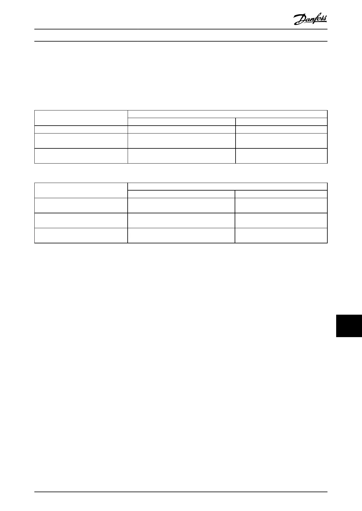
The drive size and power rating determine the layout of the DC capacitor bank. Use Table 13.3 and Table 13.4 to nd the
capacitor bank layout and fastener locations for a particular drive. Each illustration includes a table that lists which fasteners
are screws or standos, and which DC bus plate or midplate they secure.
Illustration number Model
FC 102, FC 103, and FC 202 FC 302
Illustration 13.22 N355T4 N315T5
Illustration 13.23 N400T4
N450T4
N355T5
N400T5
Illustration 13.25 N500T4
N560T4
N450T5
N500T5
Table 13.3 DC Capacitor Bank Layout 380–500 V
Illustration number Model
FC 102, FC 103, and FC 202 FC 302
Illustration 13.24 N450T7
N500T7
N355T7
N400T7
Illustration 13.26 N560T7
N630T7
N500T7
N560T7
Illustration 13.27 N710T7
N800T7
N630T7
N710T7
Table 13.4 DC Capacitor Bank Layout 525–690 V
E1h–E4h Drive Disassembly a... Service Guide
MG94A502 Danfoss A/S © 02/2019 All rights reserved. 301
13 13
 Loading...


