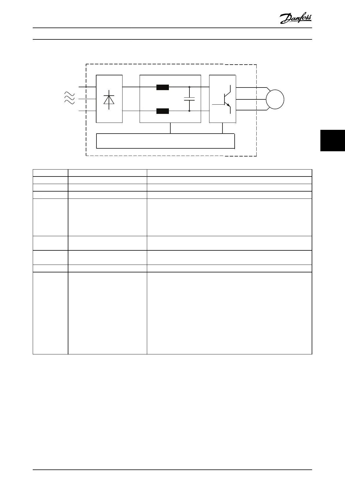
Area Title Functions
1 Mains input Provides 3-phase AC mains power input to the drive module.
2 Input rectier section Converts mains input AC voltage into DC voltage.
3 Intermediate DC bus section Acts as a lter and stores energy in the form of DC voltage.
4 DC reactors
•
Filter the DC-link voltage.
•
Reduce RMS current.
•
Raise the power factor reected back to the line.
•
Reduce harmonics on the AC input.
5 Capacitor bank Stores the DC power and provides ride-through protection for short power
losses.
6 Inverter section Converts the DC voltage into a variable, controlled PWM AC output voltage to
the motor.
7 Motor output Sends output to the motor being controlled.
8 Control
•
Monitors input and motor current to provide ecient operation and control.
•
Monitors the user interface and performs external commands.
•
Can provide status output and control.
•
Includes the power card, fan power card (in E-sized drives only), and inrush
card.
•
In a parallel drive system, a ribbon cable links the power card to the MDCIC
on the control shelf. The MDCIC provides supervision over the drive modules
in the system.
Illustration 5.1 Drive Module Basic Block Diagram
Internal Drive Operation Service Guide
MG94A502 Danfoss A/S © 02/2019 All rights reserved. 43
5 5
 Loading...


