VFD500 high performance vector control frequency inverter user manual Chapter 5 function code table
Logic block 1
input source
Unit’digit:parameter 1 bit selection
0-F (Represent 0-15),P44.18 corresponds to
0-15 bit
Ten’digit:parameter 2 bit selection
0-F (Represent 0-15),P44.19 corresponds to
0-15 bit
0:no function;1:and;
2:or;
3:not and;
4:not or;
5: exclusive OR
6:Ref=1 effective;Ref2=1 ineffective
7:Ref1 up effective,Ref2 up ineffective
8:Ref1 up and signal reverse
9:Ref1 up and output 200ms pulse width
Logic block 2
threshold
parameter 1
00.00-98.99(function code index)
Logic block 2
threshold
parameter2
00.00-98.99(function code index)
Logic block 2
input source
Unit’digit:parameter 1 bit selection
0-F (Represent 0-15),P44.22 corresponds to
0-15 bit
Ten’digit:parameter 2 bit selection
0-F (Represent 0-15),P44.23 corresponds to
0-15 bit
0:no function;
1:and;
2:or;
3:not and;
4:not or;
5: exclusive OR
6:Ref=1 effective;Ref2=1 ineffective
7:Ref1 up effective,Ref2 up ineffective
8:Ref1 up and signal reverse
9:Ref1 up and output 200ms pulse width
Logic block 3
threshold
parameter 1
00.00-98.99(function code index)
Logic block 3
threshold
parameter2
00.00-98.99(function code index)
Logic block 3
input source
Unit’digit:parameter 1 bit selection
0-F (Represent 0-15),P44.26 corresponds to
0-15 bit
Ten’digit:parameter 2 bit selection
0-F (Represent 0-15),P44.27 corresponds to
0-15 bit
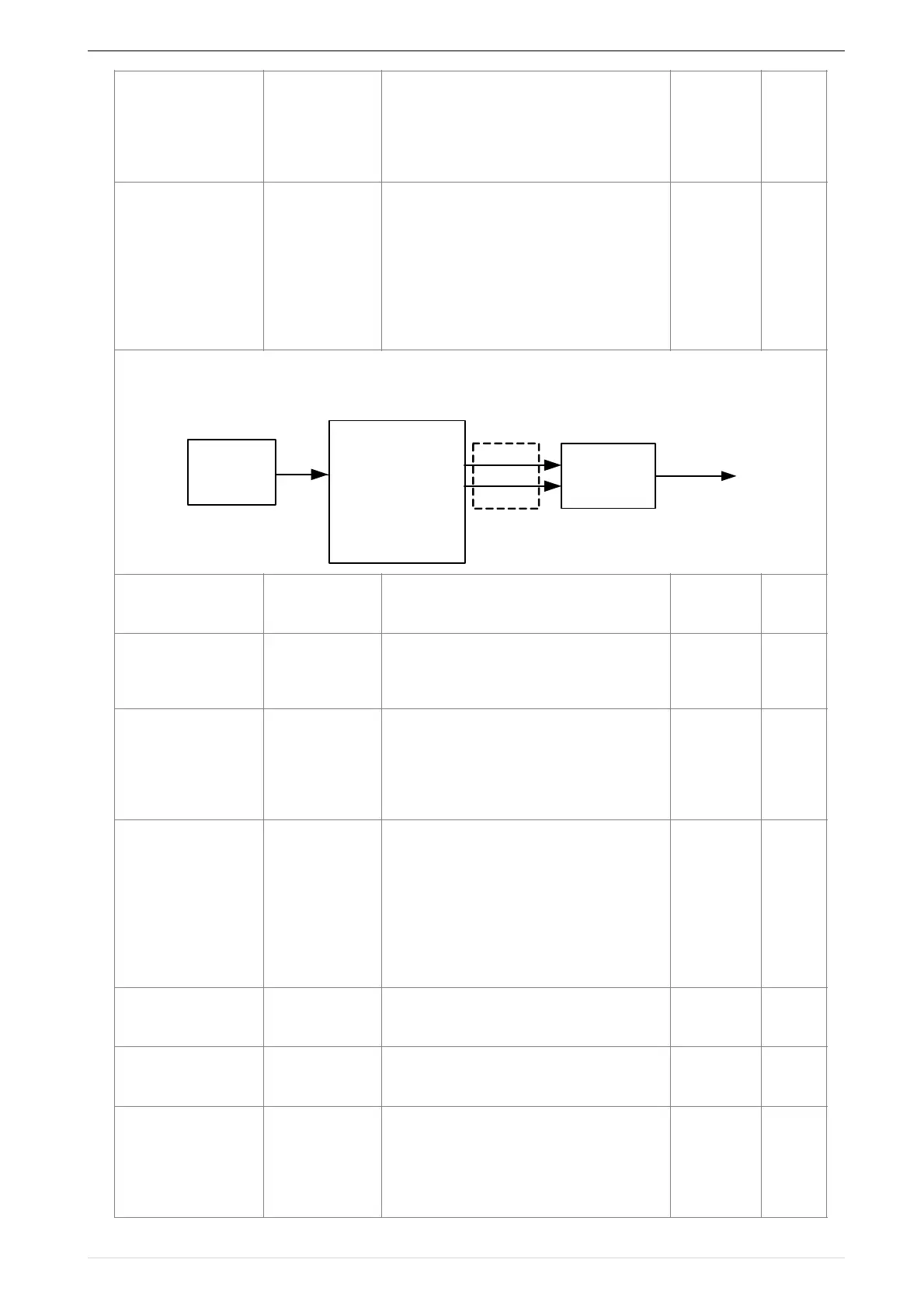
VFD500 built-in 4 logical units. The logic unit can perform any one of 0-15 bits of any parameter 1 and any one of
0-15 bits of any parameter 2 for logic processing. The condition is true output 1, otherwise 0 is output. Logic unit
output can be used as DI, VDI, delay unit and other inputs, DO, relays and other output, the user can more
flexible access to the required logic. The schematic block diagram of the logic unit 1 is as follows.
!
P44.18
Parameter 1
P44.19
parameter 2
P44.21
Logical
function
processing
P44.20
Parameter bit
selection
Units digit:select
1bit parameter
Tens digit:select
2bit parameter
Ref1
Ref2
Logical unit input
Logical unit
output
 Loading...

