◆ Open collector type, push-pull output type encoder wiring:
Select the encoder power supply through SW3 on the PG card, SW1 and SW2 to the OC side, as shown
below::
! !
Chart 7-5 Collector open type, push-pull output type encoder DIP switch selection
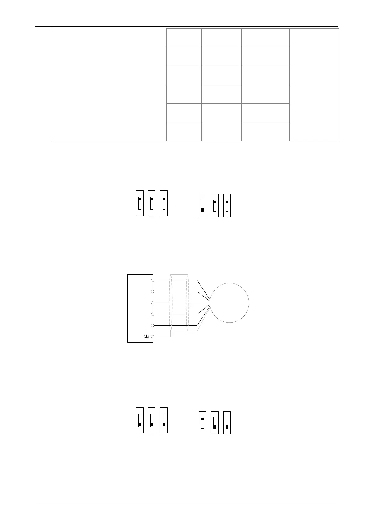
When wiring, the /A, /B, /Z terminals of the PG card are not wired, and the signal output of the
encoder is connected to the A, B, and Z terminals of the PG card, as shown in the figure below.:
!
Chart 7-6 Collector open type, push-pull output type encoder wiring diagram
◆ Differential output encoder wiring:
Select the encoder power supply through SW3 on the PG card, SW1 and SW2 to the TP side, as
shown below:
! !
Chart 7-7 Differential output type encoder DIP switch selection
The wiring of the PG card and the encoder are connected one by one according to the silkscreen.
(2)Incremental encoder PG card with Frequency division
 Loading...

