3 Mechanical Installation
3.1 How to Get Started
This chapter covers mechanical and electrical installations
to and from power terminals and control card terminals.
Electrical installation of options is described in the relevant
Operating Instructions and Design Guide.
The frequency converter is designed to achieve a quick
and EMC-correct installation by following the steps
described below.
WARNING
Read the safety instructions before installing the unit.
Failure to follow recommendations could result in death
or serious injury.
Mechanical Installation
•
Mechanical mounting
Electrical Installation
•
Connection to Mains and Protecting Earth
•
Motor connection and cables
•
Fuses and circuit breakers
•
Control terminals - cables
Quick Setup
•
Local Control Panel, LCP
•
Automatic Motor Adaptation, AMA
•
Programming
Frame size is depending on enclosure type, power range
and mains voltage.
M
3
96 97 9998
37
91 92 93
12
L1
W PEVU
F1
L2
L3
PE
130BA015.13
1
18
81 82
R+R-
95
55
50
53
27
88
89
DC- DC+
L1 L2 PEL3
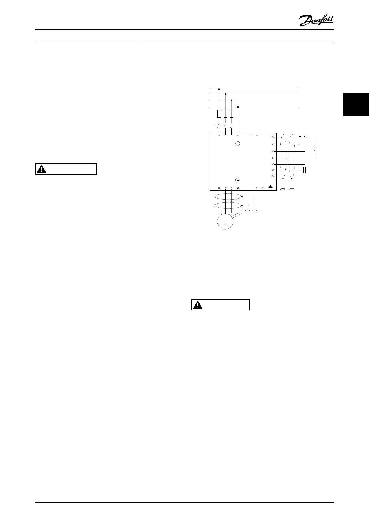
Illustration 3.1 Diagram showing basic installation including
mains, motor, start/stop key, and potentiometer for speed
adjustment.
3.2 Pre-installation
3.2.1 Planning the Installation Site
CAUTION
Before performing the installation it is important to plan
the installation of the frequency converter. Neglecting
this may result in extra work during and after instal-
lation.
Select the best possible operation site by considering
the following (see details on the following pages, and
the respective Design Guides)
•
Ambient operating temperature
•
Installation method
•
How to cool the unit
•
Position of the frequency converter
•
Cable routing
•
Ensure the power source supplies the correct
voltage and necessary current
•
Ensure that the motor current rating is within the
maximum current from the frequency converter
•
If the frequency converter is without built-in
fuses, ensure that the external fuses are rated
correctly.
Mechanical Installation
VLT HVAC Drive FC 102 Operating Instructions
MG11F402 - Rev. 2013-12-16 9
3 3
 Loading...


