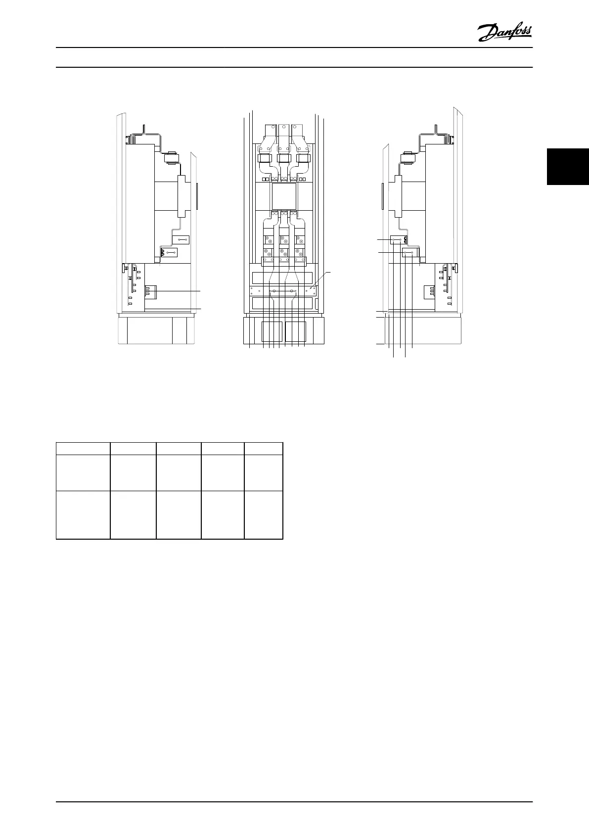
Terminal locations - Options Cabinet with circuit breaker/ molded case switch (F3 and F4)
0.0 [0.00]
134.6 [5.30]
104.3 [4.11]
0.0 [0.00]
179.3 [7.06]
219.6 [8.65]
294.6 [11.60]
334.8 [13.18]
409.8 [16.14]
436.9 [17.20]
0.0 [0.00]
532.9 [20.98]
0.0 [0.00]
44.4 [1.75]
244.4 [9.62]
154.0 [6.06]
344.0 [13.54]
1
2
3
4
5
130BA852.11
Illustration 3.35 Terminal Locations - Options Cabinet with Circuit Breaker/Molded Case Switch (Left Side, Front and Right Side View).
The Gland Plate is 42 mm below .0 Level.
1) Earth Ground Bar
Power size 2 3 4 5
500 kW (480
V), 710-800
kW (690 V)
34.9 86.9 122.2 174.2
560-1000 kW
(480 V),
900-1400 kW
(690 V)
46.3 98.3 119.0 171.0
Table 3.10 Dimensions for Terminal
3.3.6 Cooling and Airflow
Cooling
Cooling can be obtained in different ways, by using the
cooling ducts in the bottom and the top of the unit, by
taking air in and out the back of the unit or by combining
the cooling possibilities.
Duct cooling
A dedicated option has been developed to optimize instal-
lation of IP00/chassis frequency converters in Rittal TS8
enclosures utilizing the fan of the frequency converter for
forced air cooling of the backchannel. The air out of the
top of the enclosure could but ducted outside a facility so
the heat loses from the backchannel are not dissipated
within the control room reducing air-conditioning
requirements of the facility.
See
chapter 3.4.1 Installation of Duct Cooling Kit in Rittal
Enclosures, for further information.
Back cooling
The backchannel air can also be ventilated in and out the
back of a Rittal TS8 enclosure. This offers a solution where
the backchannel could take air from outside the facility
and return the heat loses outside the facility thus reducing
air-conditioning requirements.
Mechanical Installation VLT HVAC Drive FC 102 Operating Instructions
MG11F402 - Rev. 2013-12-16 33
3 3
 Loading...


