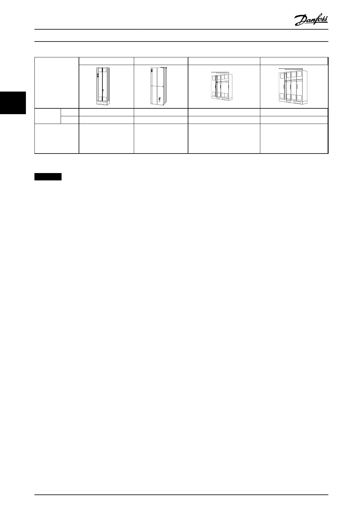
Enclosure type E1 E2 F1/F3 F2/F4
Enclosure
protection
IP 21/54 00 21/54 21/54
NEMA Type 1/Type 12 Chassis Type 1/Type 12 Type 1/Type 12
Normal overload
rated power -
110% overload
torque
315 - 450 kW at 400 V
(380 - 480 V)
450 - 630 kW at 690 V
(525-690 V)
315 - 450 kW at 400 V
(380 - 480 V)
450 - 630 kW at 690 V
(525-690 V)
500 - 710 kW at 400 V
(380 - 480 V)
710 - 900 kW at 690 V
(525-690 V)
800 - 1000 kW at 400 V
(380 - 480 V)
1000 - 1400 kW at 690 V
(525-690 V)
Table 3.6
NOTICE
The F enclosures are available in 4 different sizes, F1, F2, F3 and F4 The F1 and F2 consist of an inverter cabinet on the
right and rectifier cabinet on the left. The F3 and F4 have an additional options cabinet left of the rectifier cabinet. The
F3 is an F1 with an additional options cabinet. The F4 is an F2 with an additional options cabinet.
3.3 Mechanical Installation
Preparation of the mechanical installation of the frequency
converter must be done carefully to ensure a proper result
and to avoid additional work during installation. Start
taking a close look at the mechanical drawings at the end
of this instruction to become familiar with the space
demands.
3.3.1 Tools Needed
To perform the mechanical installation the following
tools are needed:
•
Drill with 10 or 12 mm drill
•
Tape measure
•
Wrench with relevant metric sockets (7-17mm)
•
Extensions to wrench
•
Sheet metal punch for conduits or cable glands
in IP21/Nema 1 and IP54 units
•
Lifting bar to lift the unit (rod or tube max. Ø 5
mm (1 inch), able to lift minimum 400 kg (880
lbs).
•
Crane or other lifting aid to place the frequency
converter in position
•
A Torx T50 tool is needed to install the E1 in IP21
and IP54 enclosure types.
Mechanical Installation VLT HVAC Drive FC 102 Operating Instructions
20 MG11F402 - Rev. 2013-12-16
33
 Loading...


