S1 F1
F1
DC ‘-’
DC ‘+’
1739.1
805.0
765.0
1694.1
1654.1
710.0
130BB377.10
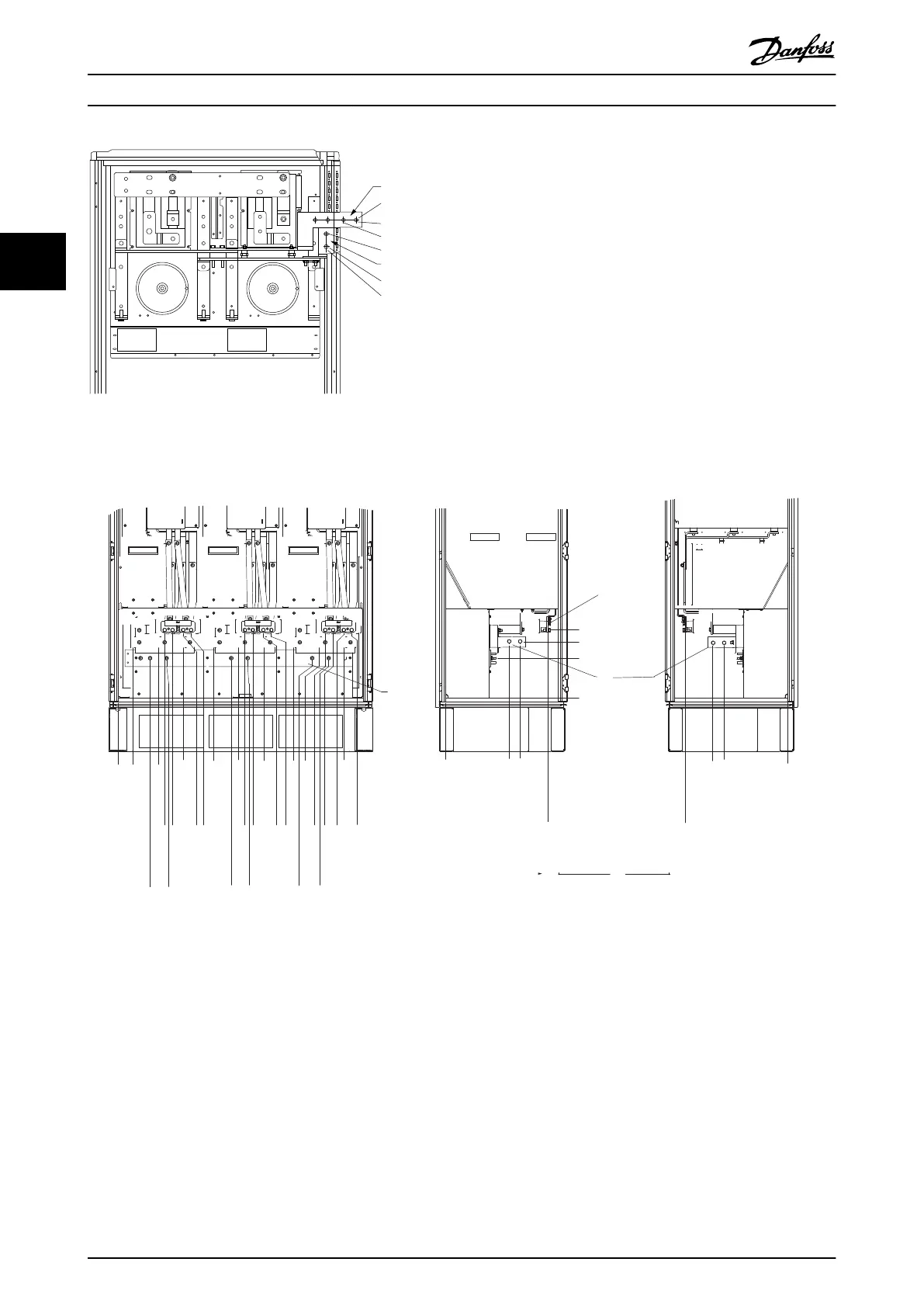
Illustration 3.30 Terminal Locations - Regen Terminals - F1 and
F3
Terminal locations - enclosure types F2 and F4
287.4 [11.32]
0.0 [0.00]
339.4 [13.36]
253.1 [9.96]
0.0 [0.00]
287.4 [11.32]
0.0 [0.00]
339.4 [13.36]
465.6 [18.33]
465.6 [18.33]
308.3 [12.14]
180.3 [7.10]
210.1 [8.27]
0.0 [0.00]
66.4 [2.61]
181.4 [7.14]
296.4 [11.67]
431.0 [16.97]
546.0 [21.50]
661.0 [26.03]
795.7 [31.33]
910.7 [35.85]
1025.7 [40.38]
246.1 [9.69]
294.1 [11.58]
330.1 [13.00]
574.7 [22.63]
610.7 [24.04]
658.7 [25.93]
694.7 [27.35]
939.4 [36.98]
975.4 [38.40]
1023.4 [40.29]
1059.4 [41.71]
144.3 [5.68]
219.3 [8.63]
512.3 [20.17]
587.3 [23.12]
880.3 [34.66]
955.3 [37.61]
6
4
130BA850.12
FASTENER TORQUE: MIO 19 Nm (14 FT -LB)
U/T1 96 V/T2 97 W/T3 98
FASTENER TORQUE: MIO 19 Nm (14 FT -LB)
U/T1 96 V/T2 97 W/T3 98
FASTENER TORQUE: MIO 19 Nm (14 FT -LB)
U/T1 96 V/T2 97 W/T3 98
1
2
3
4
5
Illustration 3.31 Terminal Locations - Inverter Cabinet - F2 and F4 (Front, Left and Right Side View). The Gland Plate is 42 mm
below .0 Level.
1) Earth Ground Bar
Mechanical Installation VLT HVAC Drive FC 102 Operating Instructions
30 MG11F402 - Rev. 2013-12-16
33
 Loading...


