6.3.8 6-** Analog In/Out
Parameter group for configuration of the analog input and output.
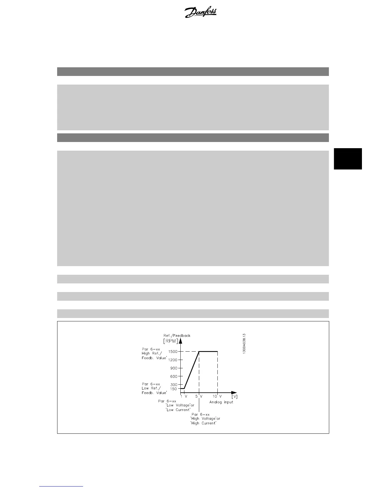
6-00 Live Zero Timeout Time
Range: Function:
10 s* [1 - 99 s] Enter the Live Zero Time-out time period. Live Zero Time-out Time is active for analog inputs, i.e.
terminal 53 or terminal 54, used as reference or feedback sources. If the reference signal value
associated with the selected current input falls below 50% of the value set in par. 6-10
Terminal 53
Low Voltage
, par. 6-12
Terminal 53 Low Current
, par. 6-20
Terminal 54 Low Voltage
or
par. 6-22
Terminal 54 Low Current
for a time period longer than the time set in par. 6-00
Live Zero
Timeout Time
, the function selected in par. 6-01
Live Zero Timeout Function
will be activated.
6-01 Live Zero Timeout Function
Option: Function:
Select the time-out function. The function set in par. 6-01
Live Zero Timeout Function
will be acti-
vated if the input signal on terminal 53 or 54 is below 50% of the value in par. 6-10
Terminal 53
Low Voltage
, par. 6-12
Terminal 53 Low Current
, par. 6-20
Terminal 54 Low Voltage
or
par. 6-22
Terminal 54 Low Current
for a time period defined in par. 6-00
Live Zero Timeout Time
.
If several time-outs occur simultaneously, the frequency converter prioritises the time-out functions
as follows:
1. Par. 6-01
Live Zero Timeout Function
2. Par. 8-04
Control Timeout Function
The output frequency of the frequency converter can be:
• [1] frozen at the present value
• [2] overruled to stop
• [3] overruled to jog speed
• [4] overruled to max. speed
• [5] overruled to stop with subsequent trip
[0] * Off
[1] Freeze output
[2] Stop
[3] Jogging
[4] Max. speed
[5] Stop and trip
VLT AQUA Low Harmonic Drive Operating In-
structions 6 How to Programme the Low Harmonic Drive
MG.20.T1.02 - VLT
®
is a registered Danfoss trademark 105
6

 Loading...


