4.7 Connection Examples for Control of Motor with External Signal Pro-
vider
NB!
The following examples refer only to the drive control card (right LCP),
not
the filter.
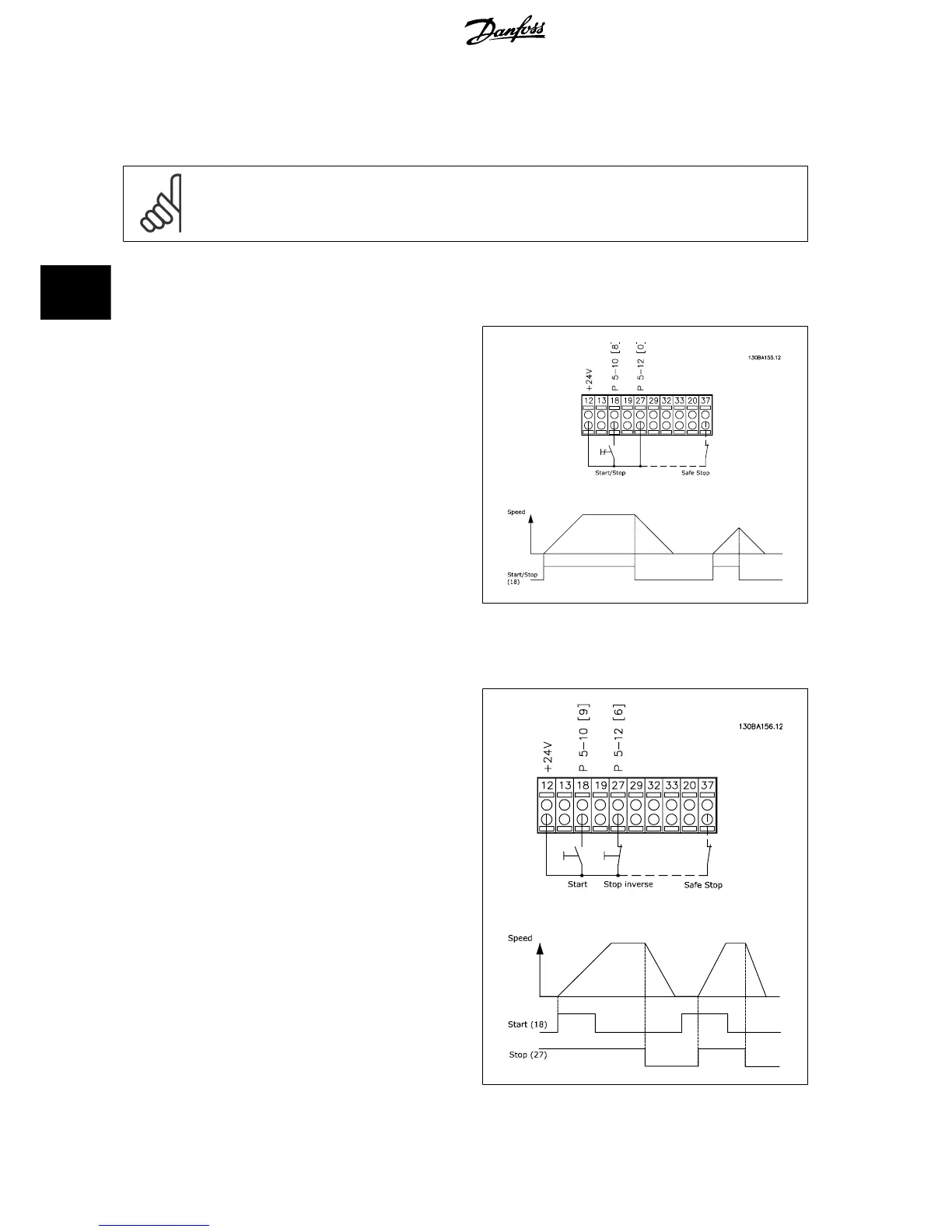
4.7.1 Start/Stop
Terminal 18 = par. 5-10
Terminal 18 Digital Input
[8]
Start
Terminal 27 = par. 5-12
Terminal 27 Digital Input
[0]
No operation
(De-
fault
coast inverse
)
Terminal 37 = Safe stop
4.7.2 Pulse Start/Stop
Terminal 18 = par. 5-10
Terminal 18 Digital Input
[9]
Latched start
Terminal 27= par. 5-12
Terminal 27 Digital Input
[6]
Stop inverse
Terminal 37 = Safe stop
4 How to Install
VLT AQUA Low Harmonic Drive Operating In-
structions
60 MG.20.T1.02 - VLT
®
is a registered Danfoss trademark
4
 Loading...


