EasyManuals Logo

Danfoss vlt aqua Operating Instructions

Danfoss vlt aqua
182 pages
To Next Page IconTo Next Page
To Previous Page IconTo Previous Page
Page #30 background imageLoading...
Page #30 background image
4.3.6 Terminal Locations - Frame size E
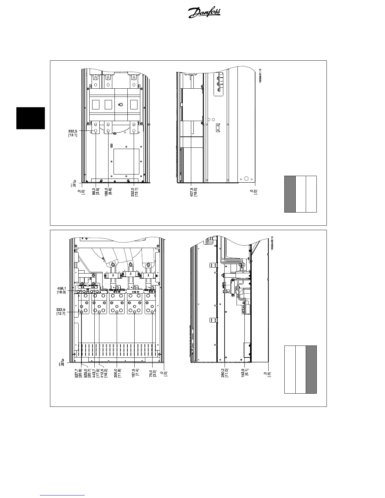
Take the following position of the terminals into consideration when designing the cable access.
Illustration 4.14: Terminal locations E3 - filter
Section shown
Illustration 4.15: Terminal locations E6 - drive
Section shown
Note that the power cables are heavy and difficult to bend. Consider the optimum position of the frequency converter for ensuring easy installation of
the cables.
Each terminal allows use of up to 4 cables with cable lugs or use of standard box lug. Earth is connected to relevant termination point in the drive.
4 How to Install
VLT AQUA Low Harmonic Drive Operating In-
structions
30 MG.20.T1.02 - VLT
®
is a registered Danfoss trademark
4

Table of Contents

Other manuals for Danfoss vlt aqua

Questions and Answers:

Question and Answer IconNeed help?

Do you have a question about the Danfoss vlt aqua and is the answer not in the manual?

Danfoss vlt aqua Specifications

General IconGeneral
Supply Voltage200-240V, 380-500V, 525-600V
EnclosureIP20
FeaturesEnergy optimization
ApprovalsCE, UL, cUL
Input Voltage Range200-240V, 380-500V, 525-600V
Output Voltage Range0 to supply voltage
Protection FeaturesOvervoltage, Undervoltage, Overcurrent, Short circuit, Ground fault
Communication InterfacesPROFIBUS
Cooling MethodAir-cooled

Related product manuals