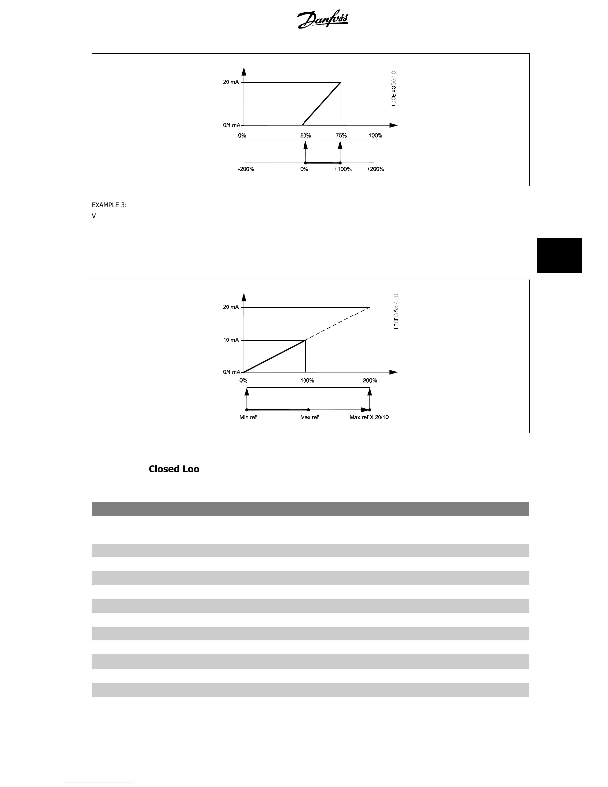
EasyManuals Logo

Danfoss vlt aqua Operating Instructions

Danfoss vlt aqua
182 pages
To Next Page IconTo Next Page
To Previous Page IconTo Previous Page
Page #109 background imageLoading...
Page #109 background image
130BA856.10
EXAMPLE 3:
Variable value= REFERENCE, range= Min ref - Max ref
Range needed for output= Min ref (0%) - Max ref (100%), 0-10 mA
Output signal 0 or 4 mA is needed at Min ref - set par. 6-51
Terminal 42 Output Min Scale
to 0%
Output signal 10 mA is needed at Max ref (100% of range) - set par. 6-52
Terminal 42 Output Max Scale
to 200%
(20 mA / 10 mA x 100%=200%).
130BA857.10
6.3.9 Drive Closed Loop, 20-**
This parameter group is used for configuring the closed loop PID Controller, that controls the output frequency of the frequency converter.
20-12 Reference/Feedback Unit
Option: Function:
[0] None
[1] * %
[5] PPM
[10] 1/min
[11] RPM
[12] Pulse/s
[20] l/s
[21] l/min
[22] l/h
[23]
m
3
/s
[24]
m
3
/min
[25]
m
3
/h
VLT AQUA Low Harmonic Drive Operating In-
structions 6 How to Programme the Low Harmonic Drive
MG.20.T1.02 - VLT
®
is a registered Danfoss trademark 109
6

Table of Contents

Other manuals for Danfoss vlt aqua

Questions and Answers:

Question and Answer IconNeed help?

Do you have a question about the Danfoss vlt aqua and is the answer not in the manual?

Danfoss vlt aqua Specifications

General IconGeneral
Supply Voltage200-240V, 380-500V, 525-600V
EnclosureIP20
FeaturesEnergy optimization
ApprovalsCE, UL, cUL
Input Voltage Range200-240V, 380-500V, 525-600V
Output Voltage Range0 to supply voltage
Protection FeaturesOvervoltage, Undervoltage, Overcurrent, Short circuit, Ground fault
Communication InterfacesPROFIBUS
Cooling MethodAir-cooled

Related product manuals