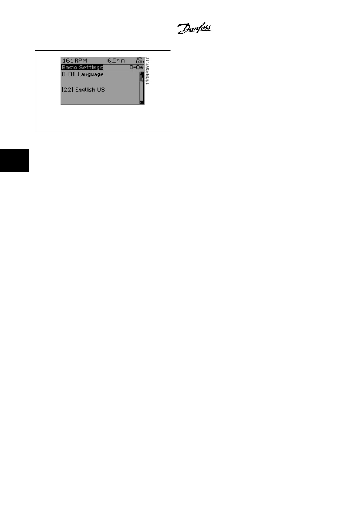
Figure 5.10: Display example.
5.2 Commonly Used Parameters - Explanations
5.2.1 Main Menu
The main menu includes all available parameters in the VLT
®
AQUA Drive FC 200 adjustable frequency drive.
All parameters are grouped logically with a group name indicating the function of the parameter group.
All parameters are listed by name and number in the section
Parameter Options
in this Instruction Manual.
All parameters included in the quick menus (Q1, Q2, Q3, Q5 and Q6) can be found in the following.
Some of the most commonly used parameters for VLT
®
AQUA Drive applications are also explained in the following section.
For a detailed explanation of all parameters, please refer to the VLT
®
AQUA Drive Programming Guide MG.20.OX.YY which is available at www.danfoss.com
or by ordering it from the local Danfoss office.
5 How to program the adjustable frequency
drive
VLT AQUA High Power Instruction Manual
5-8
MG.20.P3.22 - VLT
®
is a registered Danfoss trademark
5