EasyManuals Logo

Danfoss vlt aqua User Manual

Danfoss vlt aqua
205 pages
To Next Page IconTo Next Page
To Previous Page IconTo Previous Page
Page #78 background imageLoading...
Page #78 background image
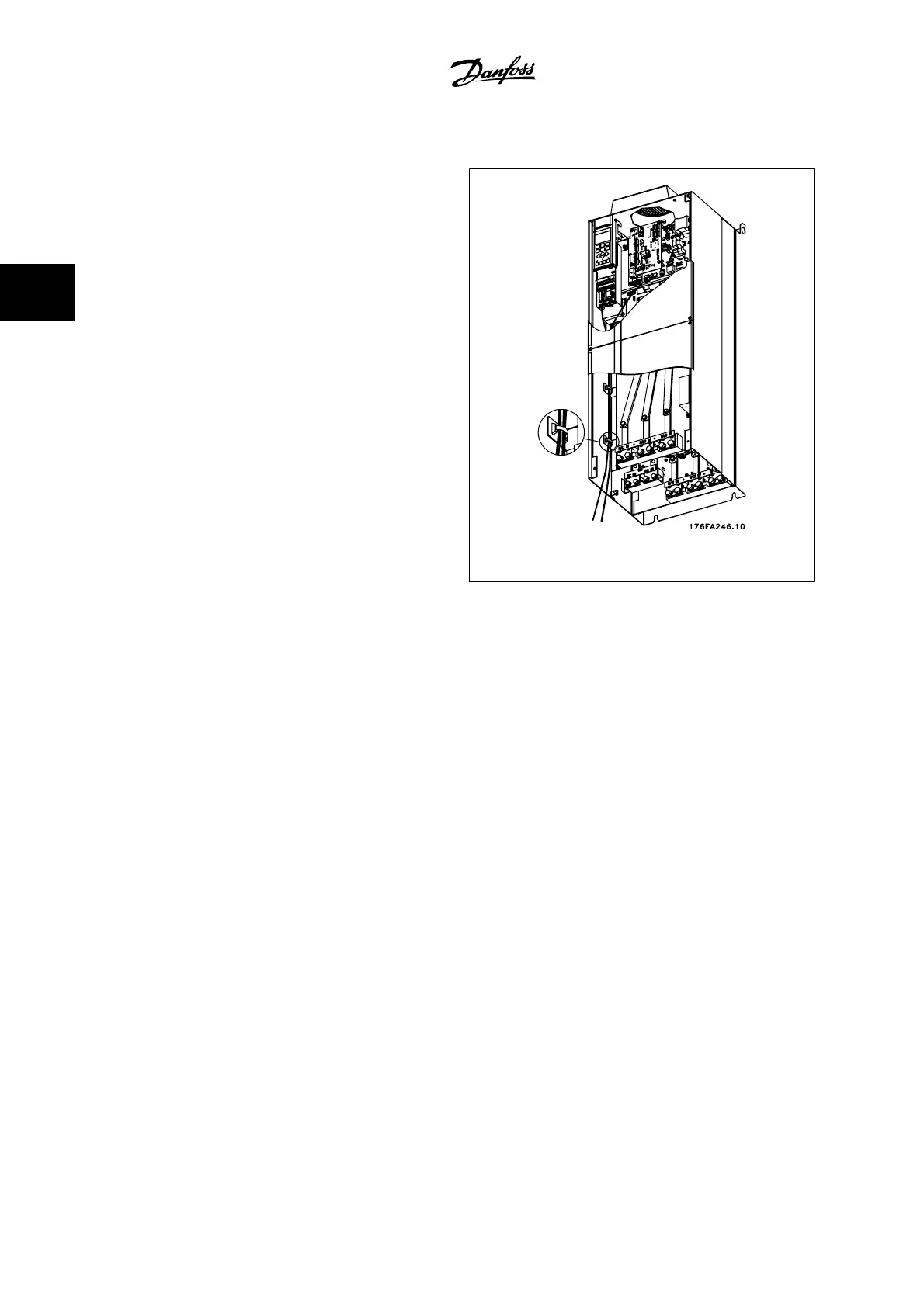
3.6.20 Control cable routing
Tie down all control wires to the designated control cable routing as
shown in the picture. Remember to connect the shields in a proper way
to ensure optimum electrical immunity.
Serial communication bus connection
Connections are made to the relevant options on the control card. For
details, see the relevant serial communication bus instruction. The cable
must be placed to the left inside the adjustable frequency drive and tied
down together with other control wires (see picture).
Figure 3.51: Wire path for control wiring.
3 How to Install VLT AQUA High Power Instruction Manual
3-64
MG.20.P3.22 - VLT
®
is a registered Danfoss trademark
3

Other manuals for Danfoss vlt aqua

Questions and Answers:

Question and Answer IconNeed help?

Do you have a question about the Danfoss vlt aqua and is the answer not in the manual?

Danfoss vlt aqua Specifications

General IconGeneral
Supply Voltage200-240V, 380-500V, 525-600V
EnclosureIP20
FeaturesEnergy optimization
ApprovalsCE, UL, cUL
Input Voltage Range200-240V, 380-500V, 525-600V
Output Voltage Range0 to supply voltage
Protection FeaturesOvervoltage, Undervoltage, Overcurrent, Short circuit, Ground fault
Communication InterfacesPROFIBUS
Cooling MethodAir-cooled

Related product manuals