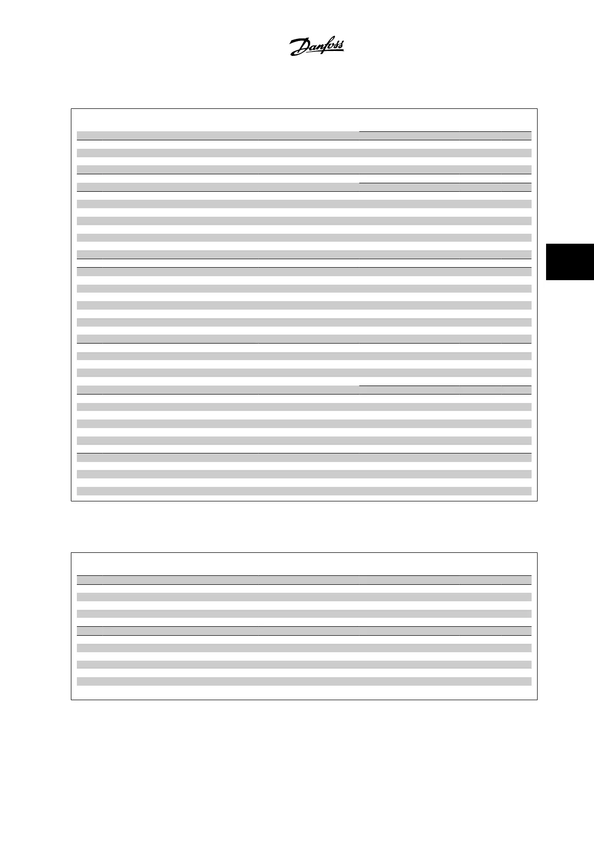
5.3.3 1-** Load/Motor
Par.
No. #
Parameter description Default value 4-set-up Change dur-
ing operation
Conver-
sion index
Type
1-0* General Settings
1-00 Configuration Mode null All set-ups TRUE - Uint8
1-01 Motor Control Principle null All set-ups FALSE - Uint8
1-03 Torque Characteristics [3] Auto Energy Optim. VT All set-ups TRUE - Uint8
1-1* Motor Selection
1-10 Motor Construction [0] Asynchronous All set-ups FALSE - Uint8
1-2* Motor Data
1-20 Motor Power [kW] ExpressionLimit All set-ups FALSE 1 Uint32
1-21 Motor Power [HP] ExpressionLimit All set-ups FALSE -2 Uint32
1-22 Motor Voltage ExpressionLimit All set-ups FALSE 0 Uint16
1-23 Motor Frequency ExpressionLimit All set-ups FALSE 0 Uint16
1-24 Motor Current ExpressionLimit All set-ups FALSE -2 Uint32
1-25 Motor Nominal Speed ExpressionLimit All set-ups FALSE 67 Uint16
1-28 Motor Rotation Check [0] OFF All set-ups FALSE - Uint8
1-29 Automatic Motor Adaptation (AMA) [0] Off All set-ups FALSE - Uint8
1-3* Addl. Motor Data
1-30 Stator Resistance (Rs) ExpressionLimit All set-ups FALSE -4 Uint32
1-31 Rotor Resistance (Rr) ExpressionLimit All set-ups FALSE -4 Uint32
1-32 Stator Reactance (Xs) ExpressionLimit All set-ups FALSE -4 Uint32
1-33 Stator Leakage Reactance (X1) ExpressionLimit All set-ups FALSE -4 Uint32
1-34 Rotor Leakage Reactance (X2) ExpressionLimit All set-ups FALSE -4 Uint32
1-35 Main Reactance (Xh) ExpressionLimit All set-ups FALSE -4 Uint32
1-36 Iron Loss Resistance (Rfe) ExpressionLimit All set-ups FALSE -3 Uint32
1-39 Motor Poles ExpressionLimit All set-ups FALSE 0 Uint8
1-5* Load-Indep. Setting
1-50 Motor Magnetization at Zero Speed 100 % All set-ups TRUE 0 Uint16
1-51 Min Speed Normal Magnetizing [RPM] ExpressionLimit All set-ups TRUE 67 Uint16
1-52 Min Speed Normal Magnetizing [Hz] ExpressionLimit All set-ups TRUE -1 Uint16
1-55 U/f Characteristic - U ExpressionLimit All set-ups TRUE -1 Uint16
1-56
U/f Characteristic - F ExpressionLimit All set-ups TRUE -1 Uint16
1-6* Load-Depend. Settg.
1-60 Low Speed Load Compensation 100 % All set-ups TRUE 0 Int16
1-61 High Speed Load Compensation 100 % All set-ups TRUE 0 Int16
1-62 Slip Compensation 0 % All set-ups TRUE 0 Int16
1-63 Slip Compensation Time Constant ExpressionLimit All set-ups TRUE -2 Uint16
1-64 Resonance Dampening 100 % All set-ups TRUE 0 Uint16
1-65 Resonance Dampening Time Constant 5 ms All set-ups TRUE -3 Uint8
1-7* Start Adjustments
1-71 Start Delay 0.0 s All set-ups TRUE -1 Uint16
1-73 Flying Start [0] Disabled All set-ups FALSE - Uint8
1-74 Start Speed [RPM] ExpressionLimit All set-ups TRUE 67 Uint16
1-75 Start Speed [Hz] ExpressionLimit All set-ups TRUE -1 Uint16
1-76 Start Current 0.00 A All set-ups TRUE -2 Uint32
5.3.4 2-** Brakes
Par.
No. #
Parameter description Default value 4-set-up Change dur-
ing operation
Conver-
sion index
Type
2-0* DC Brake
2-00 DC Hold/Preheat Current 50 % All set-ups TRUE 0 Uint8
2-01 DC Brake Current 50 % All set-ups TRUE 0 Uint16
2-02 DC Braking Time 10.0 s All set-ups TRUE -1 Uint16
2-03 DC Brake Cut-in Speed [RPM] ExpressionLimit All set-ups TRUE 67 Uint16
2-04
DC Brake Cut-in Speed [Hz] ExpressionLimit All set-ups TRUE -1 Uint16
2-1* Brake Energy Funct.
2-10 Brake Function [0] Off All set-ups TRUE - Uint8
2-11 Brake Resistor (ohm) ExpressionLimit All set-ups TRUE 0 Uint16
2-12 Brake Power Limit (kW) ExpressionLimit All set-ups TRUE 0 Uint32
2-13 Brake Power Monitoring [0] Off All set-ups TRUE - Uint8
2-15 Brake Check [0] Off All set-ups TRUE - Uint8
2-16 AC Brake Max. Current 100.0 % All set-ups TRUE -1 Uint32
2-17 Over-voltage Control [2] Enabled All set-ups TRUE - Uint8
VLT AQUA High Power Instruction Manual
5 How to program the adjustable frequency
drive
MG.20.P3.22 - VLT
®
is a registered Danfoss trademark
5-51
5