EasyManuals Logo

Danfoss vlt aqua User Manual

Danfoss vlt aqua
205 pages
To Next Page IconTo Next Page
To Previous Page IconTo Previous Page
Page #29 background imageLoading...
Page #29 background image
3.3.3 Terminal locations - frame size D
Take the following terminal positions into consideration when you design for cable access.
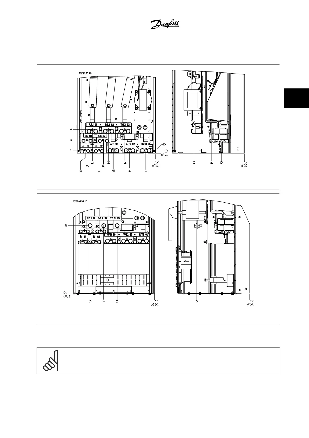
Figure 3.10: Position of power connections, frame size D3 and D4
Figure 3.11: Position of power connections with disconnect switch, frame size D1 and D2
Be aware that the power cables are heavy and hard to bend. Give thought to the optimum position of the adjustable frequency drive for ensuring easy
installation of the cables.
NOTE!
All D frames are available with standard input terminals or disconnect switch. All terminal dimensions can be found in the table on the
next page.
VLT AQUA High Power Instruction Manual 3 How to Install
MG.20.P3.22 - VLT
®
is a registered Danfoss trademark
3-15
3

Other manuals for Danfoss vlt aqua

Questions and Answers:

Question and Answer IconNeed help?

Do you have a question about the Danfoss vlt aqua and is the answer not in the manual?

Danfoss vlt aqua Specifications

General IconGeneral
Supply Voltage200-240V, 380-500V, 525-600V
EnclosureIP20
FeaturesEnergy optimization
ApprovalsCE, UL, cUL
Input Voltage Range200-240V, 380-500V, 525-600V
Output Voltage Range0 to supply voltage
Protection FeaturesOvervoltage, Undervoltage, Overcurrent, Short circuit, Ground fault
Communication InterfacesPROFIBUS
Cooling MethodAir-cooled

Related product manuals