3.3.7 Installation on the wall - IP21 (NEMA 1) and IP54 (NEMA 12) Units
This only applies to frame sizes D1 and D2 . Thought must be given to where the unit should be installed.
Take the relevant points into consideration before you select the final installation site:
• Clearance space for cooling
• Clearance for opening the door
• Cable entry clearance from the bottom
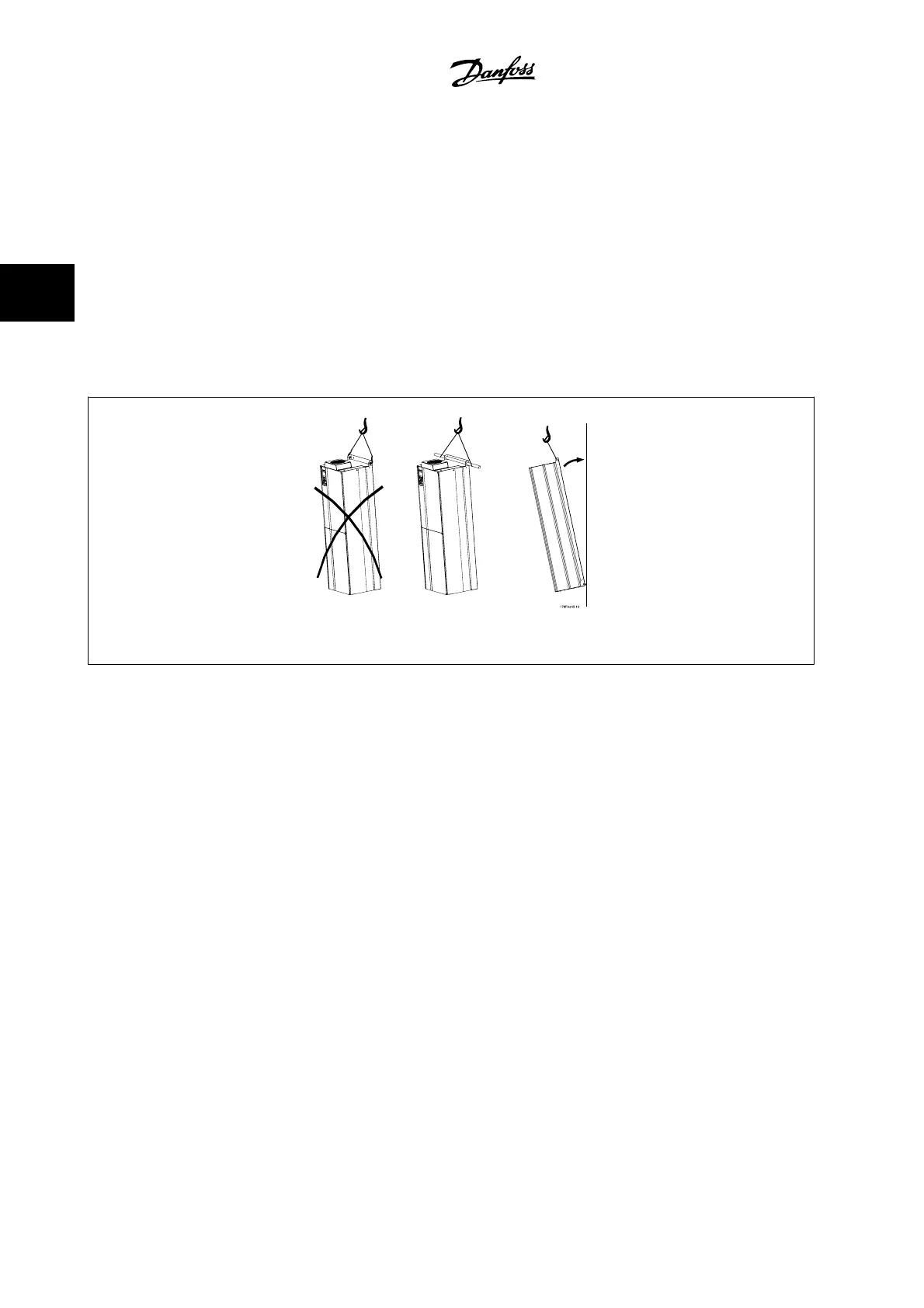
Mark the mounting holes carefully using the mounting template on the wall, and drill the holes as indicated. Ensure proper distance to the floor and the
ceiling for cooling. A minimum of 8.9 in [225 mm] below the adjustable frequency drive is needed. Mount the bolts at the bottom and lift the adjustable
frequency drive up on the bolts. Tilt the adjustable frequency drive against the wall and mount the upper bolts. Tighten all four bolts to secure the
adjustable frequency drive against the wall.
Figure 3.24: Lifting method for mounting drive on wall
3 How to Install VLT AQUA High Power Instruction Manual
3-26
MG.20.P3.22 - VLT
®
is a registered Danfoss trademark
3