EasyManuals Logo

Danfoss vlt aqua User Manual

Danfoss vlt aqua
205 pages
To Next Page IconTo Next Page
To Previous Page IconTo Previous Page
Page #50 background imageLoading...
Page #50 background image
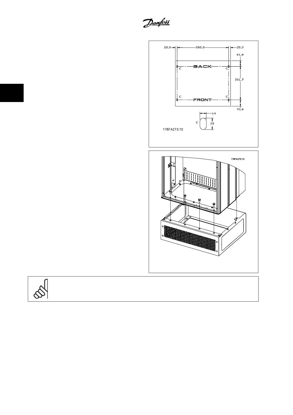
Install the pedestal on the floor. Fixing holes are to be drilled according
to this figure:
Figure 3.34: Drill master for fixing holes in floor.
Mount the drive on the pedestal and using the enclosed bolts, attach it
to the pedestal, as shown in the illustration.
Figure 3.35: Mounting the drive to the pedestal
NOTE!
Please see the
Pedestal Kit Instruction Manual, 175R5642
, for further information.
3 How to Install VLT AQUA High Power Instruction Manual
3-36
MG.20.P3.22 - VLT
®
is a registered Danfoss trademark
3

Other manuals for Danfoss vlt aqua

Questions and Answers:

Question and Answer IconNeed help?

Do you have a question about the Danfoss vlt aqua and is the answer not in the manual?

Danfoss vlt aqua Specifications

General IconGeneral
Supply Voltage200-240V, 380-500V, 525-600V
EnclosureIP20
FeaturesEnergy optimization
ApprovalsCE, UL, cUL
Input Voltage Range200-240V, 380-500V, 525-600V
Output Voltage Range0 to supply voltage
Protection FeaturesOvervoltage, Undervoltage, Overcurrent, Short circuit, Ground fault
Communication InterfacesPROFIBUS
Cooling MethodAir-cooled

Related product manuals