1) AUX Relay 5) Load sharing
01 02 03 -DC +DC
04 05 06 88 89
2) Temp Switch 6) SMPS Fuse (see fuse tables for part number)
106 104 105 7) Fan Fuse (see fuse tables for part number)
3) Line 8) AUX Fan
R S T 100 101 102 103
91 92 93 L1 L2 L1 L2
L1 L2 L3 9) Line power ground
4) Brake 10) Motor
-R +R U V W
81 82 96 97 98
T1 T2 T3
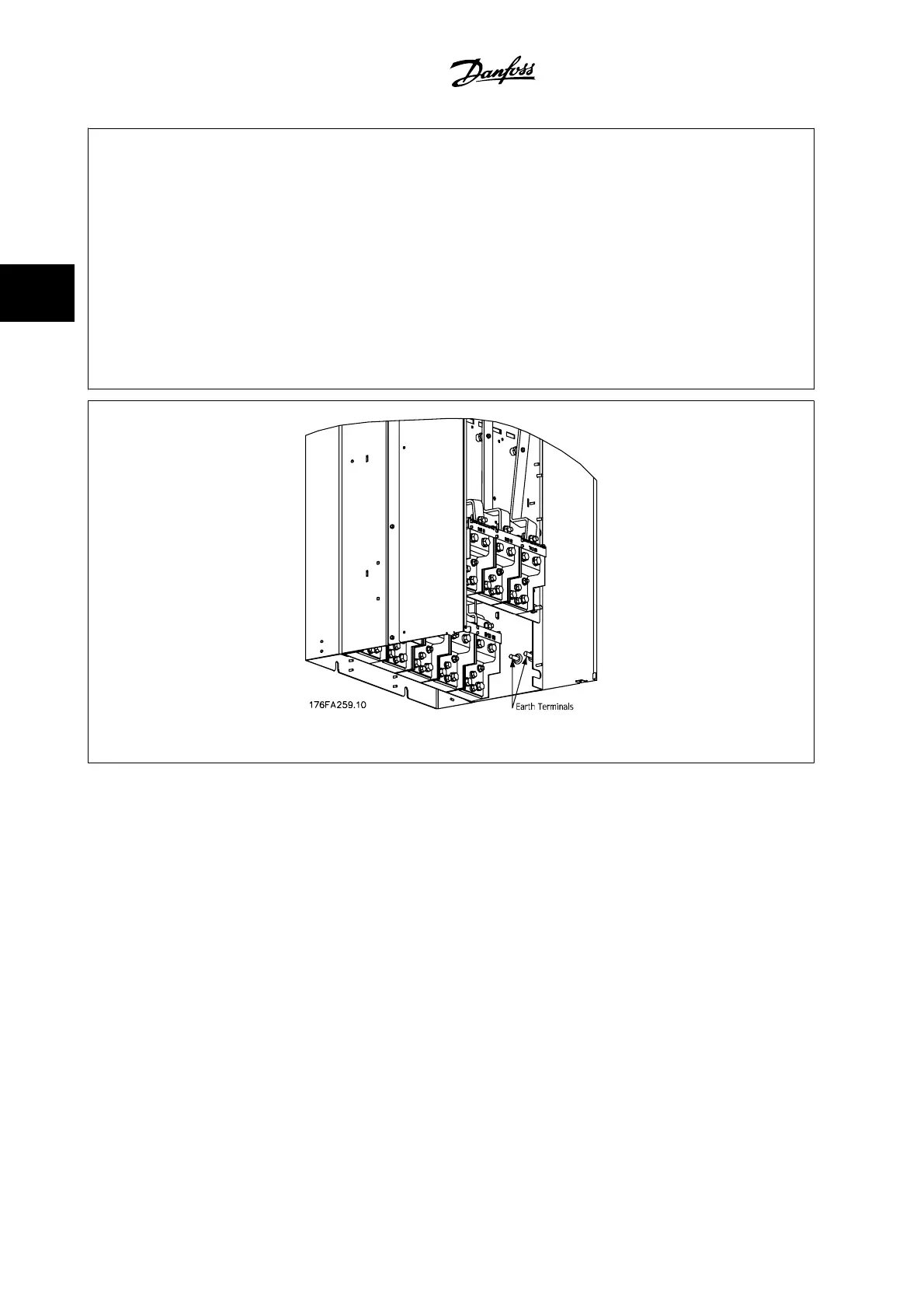
Figure 3.44: Position of ground terminals IP00, frame sizes E
3 How to Install VLT AQUA High Power Instruction Manual
3-48
MG.20.P3.22 - VLT
®
is a registered Danfoss trademark
3