EasyManuals Logo

Danfoss vlt aqua User Manual

Danfoss vlt aqua
205 pages
To Next Page IconTo Next Page
To Previous Page IconTo Previous Page
Page #66 background imageLoading...
Page #66 background image
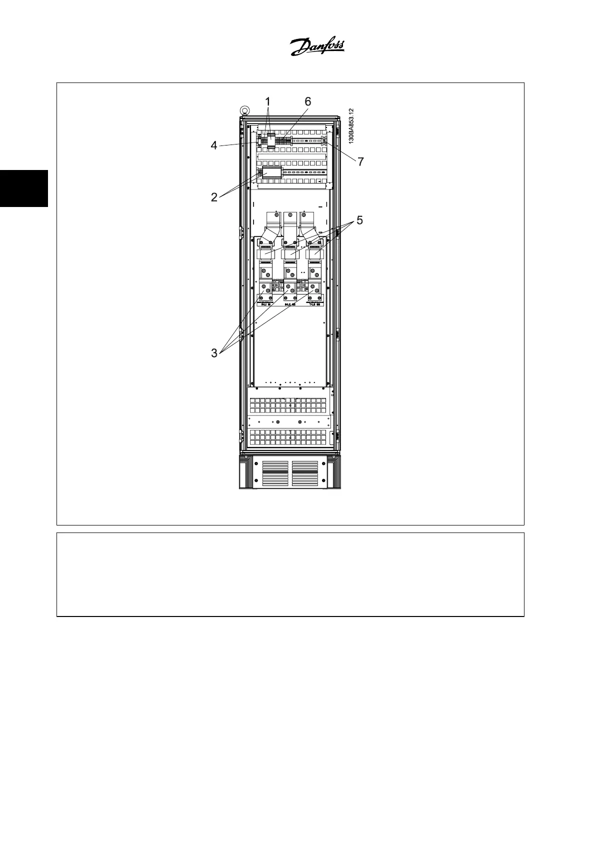
Figure 3.48: Options Cabinet, frame size F3 and F4
1) Pilz Relay Terminal 4) Safety Relay Coil Fuse with PILS Relay
2) RCD or IRM Terminal See fuse tables for part numbers
3) Line power 5) Line Fuses, F3 and F4 (3 pieces)
R S T See fuse tables for part numbers
91 92 93 6) Contactor Relay Coil (230 V AC). N/C and N/O Aux Contacts
L1 L2 L3 7) Circuit Breaker Shunt Trip Control Terminals (230 V AC or 230 V DC)
3 How to Install VLT AQUA High Power Instruction Manual
3-52
MG.20.P3.22 - VLT
®
is a registered Danfoss trademark
3

Other manuals for Danfoss vlt aqua

Questions and Answers:

Question and Answer IconNeed help?

Do you have a question about the Danfoss vlt aqua and is the answer not in the manual?

Danfoss vlt aqua Specifications

General IconGeneral
Supply Voltage200-240V, 380-500V, 525-600V
EnclosureIP20
FeaturesEnergy optimization
ApprovalsCE, UL, cUL
Input Voltage Range200-240V, 380-500V, 525-600V
Output Voltage Range0 to supply voltage
Protection FeaturesOvervoltage, Undervoltage, Overcurrent, Short circuit, Ground fault
Communication InterfacesPROFIBUS
Cooling MethodAir-cooled

Related product manuals