N O T I C E
All signals to the safety option must be PELV supplied and comply with EN IEC 60204.
Follow these guidelines to ensure proper wiring:
• Use appropriate wiring to prevent short circuits to a supply line or between the inputs.
• Use separate multi-core cable for supply voltage to avoid short circuits between the cable from the output (S37) and the 24 V DC
supply line.
• Connect shields at both ends to the grounded enclosures through a good electrical connection and through a large surface area.
• Connect cable shields as close as possible to the cabinet cable entry.
• If possible, intermediate terminals should not interrupt cable shields.
• Retain cable shields for both power cables and data cables using the appropriate EMC clamps. Ensure that the shield connection
for control cables has a low induction.
N O T I C E
If short circuits and cross circuits can be expected with safety-related signals, and if they are not detected by upstream devices,
protected cable installation is required as per EN ISO 13849-2.
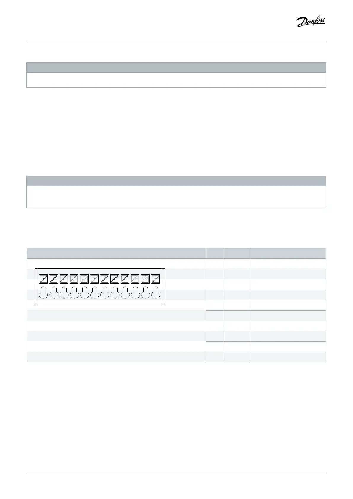
4.4.2 Connector Pin Assignment
Table 4: Connector Pin Assignment, VLT® Safety Option MCB 152
Pin Name Description
1 2 3 4 5 6 7 8 9 10 11 12
1 DI1 A Digital input 1 A channel
2 GND Ground
3 DI1 B Digital input 1 B channel
5 DI2 A Digital input 2 A channel
6 GND Ground
8 DI2 B Digital input 2 B channel
9 GND Ground
10 24 V Power output
11 GND Ground
12 S37 Safe output
Installation
Installation Guide | VLT®Safety Option MCB 152
AN327351953089en-000101 / 130R0578| 23
Danfoss A/S © 2020.02

 Loading...


