7 Parameter Setup
7.1 About Safety Parameters
This section describes the safety option parameters.
Use VLT® Motion Control Tool MCT 10 to configure the safety functions supported in VLT® Safety Option MCB 152.
Safety parameters have the following properties:
• The safety option stores 2 separate copies of the safety parameters.
• During start-up, a cyclic redundancy check (CRC) sum over the safety parameters is calculated and checked. The safety option
stores parameters in the non-volatile memory. To see the CRC value on the LCP, add parameter 42-35 S-CRC Value to the LCP small
display line.
A reset of the safety parameters to the blank initial state can be executed via MCT 10.
7.2 Parameter Lists
All safety parameters, except parameter 42-90 Restart Safe Option, can only be read from the LCP (but not changed). Use the VLT®
Motion Control Tool MCT 10 Safe Plug-in to change the parameter values.
Refer to VLT® AutomationDrive FC 301/FC 302 Programming Guide for general information about usage of conversion index and data
type.
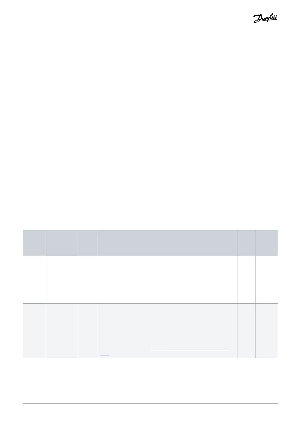
7.2.1 Parameter Group 42-2* Safe Input
Table 9: 42-2* Safe Input
Parame‐
ter
Options/
valid range
De‐
fault
value
Description Con‐
ver‐
sion
index
Data
type
42-20
Safe
Function
[0] STO
[5] Disable
[8] SO Mon
[5] Dis-
able
Select the safety function that the safety option activates when the
safe input is active. [0] STO - the safety option activates STO. [5] Disable
- the safety option ignores the current safe input. [8] SO Mon - the safe-
ty option monitors all activity on the current safe input, but does not
activate safety functions. The safety option transmits the information
to the PLC and the PLC handles the safety logic. This parameter is an
array with 2 elements. Element 0 contains DI1 settings and element 1 -
DI2 settings.
– u_int8
42-21
Type
[0] NCNC
[1] Antivalent
[2] NC
[0]
NCNC
Select the safe input type.
• [0] NCNC: A digital input is active when there is 0 V at both chan-
nels of the input.
• [1] Antivalent: A digital input is active only when there is 0 V at
channel A and 24 V at channel B.
• [2] NC: The functionality is similar to NCNC.
For more information, see
3.9.1 Allowed Sensor Types on Digital In-
puts.
– u_int8
Parameter Setup
Installation Guide | VLT®Safety Option MCB 152
AN327351953089en-000101 / 130R0578
48 | Danfoss A/S © 2020.02

 Loading...


