130BX168.10
20
19
18
17
16
15
14
13
12
11
23
22
21
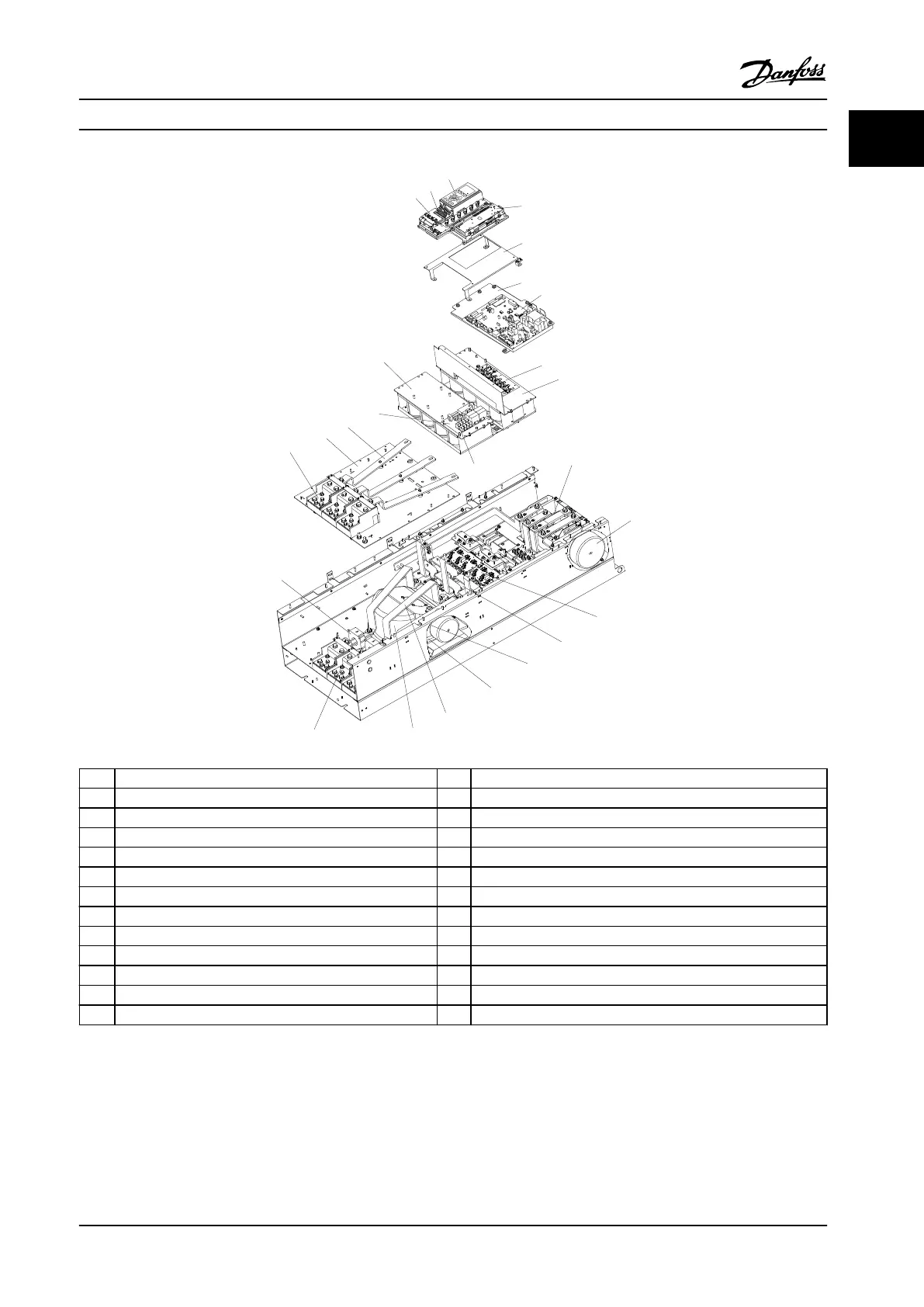
1 Control card 14 SCR and diode
2 Control input terminals 15 Fan inductor (not on all units)
3 Local control panel (LCP) 16 Soft-charge resistor assembly
4 Control card C option 17 IGBT output bus bar
5 Mounting bracket 18 Fan assembly
6 Power card mounting plate 19 Output motor terminals
7 Power card 20 Current sensor
8 IGBT gate drive card 21 Main AC power input terminals
9 Upper capacitor bank assembly 22 Input terminal mounting plate
10 Soft-charge fuses 23 AC input bus bar
11 DC inductor 24 Soft-charge card
12 Fan transformer 25 Lower capacitor bank assembly
13 IGBT module
Figure 1.4 Frame Size E9 Drive Enclosure
Introduction Installation Manual
MG37A322 Danfoss A/S © Rev. 04/2015 All rights reserved. 9
1 1

 Loading...


