1
2
3
4
5
6
7
8
PE
U
V
W
9
L1
L2
L3
PE
130BB607.10
10
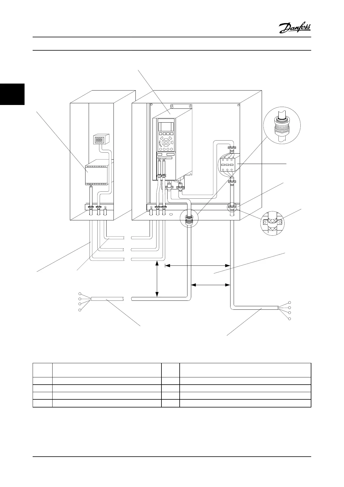
Figure 2.5 Typical Electrical Connection
1
PLC 6 Min. 7.9 in [200 mm] between control cables, motor and line
power
2 Adjustable frequency drive 7 Motor, 3-phase and PE
3 Output contactor (Generally not recommended) 8 Line power, 3-phase and reinforced PE
4 Grounding rail (PE) 9 Control wiring
5 Cable insulation (stripped) 10
Equalizing min. 0.025 in
2
[16mm
2
]
Installation
VLT
®
AutomationDrive Instruction
Manual
2-4 MG.33.AI.22 - VLT
®
is a registered Danfoss trademark
2
2

 Loading...


