•
Follow all local and national electrical codes to
ground electrical equipment properly.
•
Proper protective grounding for equipment with
ground currents higher than 3.5 mA must be
established, see Leakage Current (>3.5 mA)
•
A dedicatedground wire is required for input
power, motor power and control wiring
•
Use the clamps provided with on the equipment
for proper ground connections
•
Do not ground one Adjustable frequency drive to
another in a “daisy chain” fashion
•
Keep the ground wire connections as short as
possible
•
Use of high-strand wire to reduce electrical noise
is recommended
•
Follow the motor manufacturer wiring
requirements
2.4.2.1
Leakage Current (>3.5mA)
Follow national and local codes regarding protective
grounding of equipment with a leakage current > 3.5mA.
Adjustable frequency drive technology implies high
frequency switching at high power. This will generate a
leakage current in the ground connection. A fault current
in the Adjustable frequency drive at the output power
terminals might contain a DC component which can
charge the filter capacitors and cause a transient ground
current. The ground leakage current depends on various
system configurations including RFI filtering, shielded
motor cables, and Adjustable frequency drive power.
EN/IEC61800-5-1 (Power Drive System Product Standard)
requires special care if the leakage current exceeds 3.5mA.
Grounding must be reinforced in one of the following
ways:
•
Ground wire of at least 0.0155 in
2
[10mm
2
]
•
Two separate ground wires both complying with
the dimensioning rules
See EN 60364-5-54 § 543.7 for further information.
Using RCDs
Where residual current devices (RCDs), also known as
ground leakage circuit breakers (ELCBs), are used, comply
with the following:
Use RCDs of type B only which are capable of
detecting AC and DC currents
Use RCDs with an inrush delay to prevent faults
due to transient ground currents
Dimension RCDs according to the system configu-
ration and environmental considerations
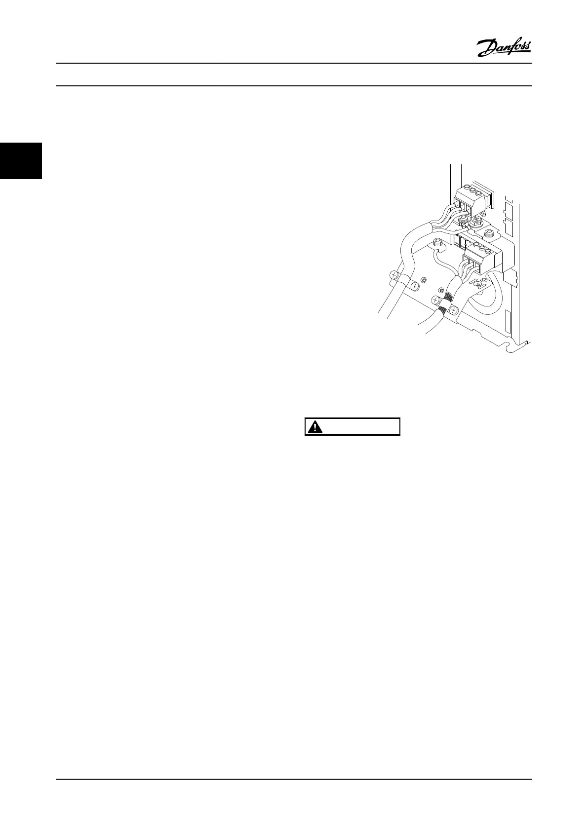
2.4.2.2
Grounding Using Shielded Cable
Grounding clamps are provided for motor wiring (see
Figure 2.7).
130BA266.10
+DC
BR-
B
MAINS
L1 L2 L3
91 92 93
RELAY 1 RELAY 2
99
- LC -
UVW
MOTOR
Figure 2.7 Grounding with Shielded Cable
2.4.3
Motor Connection
WARNING
INDUCED VOLTAGE!
Run output motor cables from multiple adjustable
frequency drives separately. Induced voltage from output
motor cables run together can charge equipment
capacitors even with the equipment turned off and locked
out. Failure to run output motor cables separately could
result in death or serious injury.
•
For maximum wire sizes, see 10.1 Power-
dependent Specifications
•
Comply with local and national electrical codes
for cable sizes.
•
Motor wiring knockouts or access panels are
provided at the base of IP21 and higher
(NEMA1/12) units
•
Do not install power factor correction capacitors
between the adjustable frequency drive and the
motor
•
Do not wire a starting or pole-changing device
between the adjustable frequency drive and the
motor.
•
Connect the 3-phase motor wiring to terminals
96 (U), 97 (V), and 98 (W).
Installation
VLT
®
AutomationDrive Instruction
Manual
2-6 MG.33.AI.22 - VLT
®
is a registered Danfoss trademark
2
2

 Loading...


