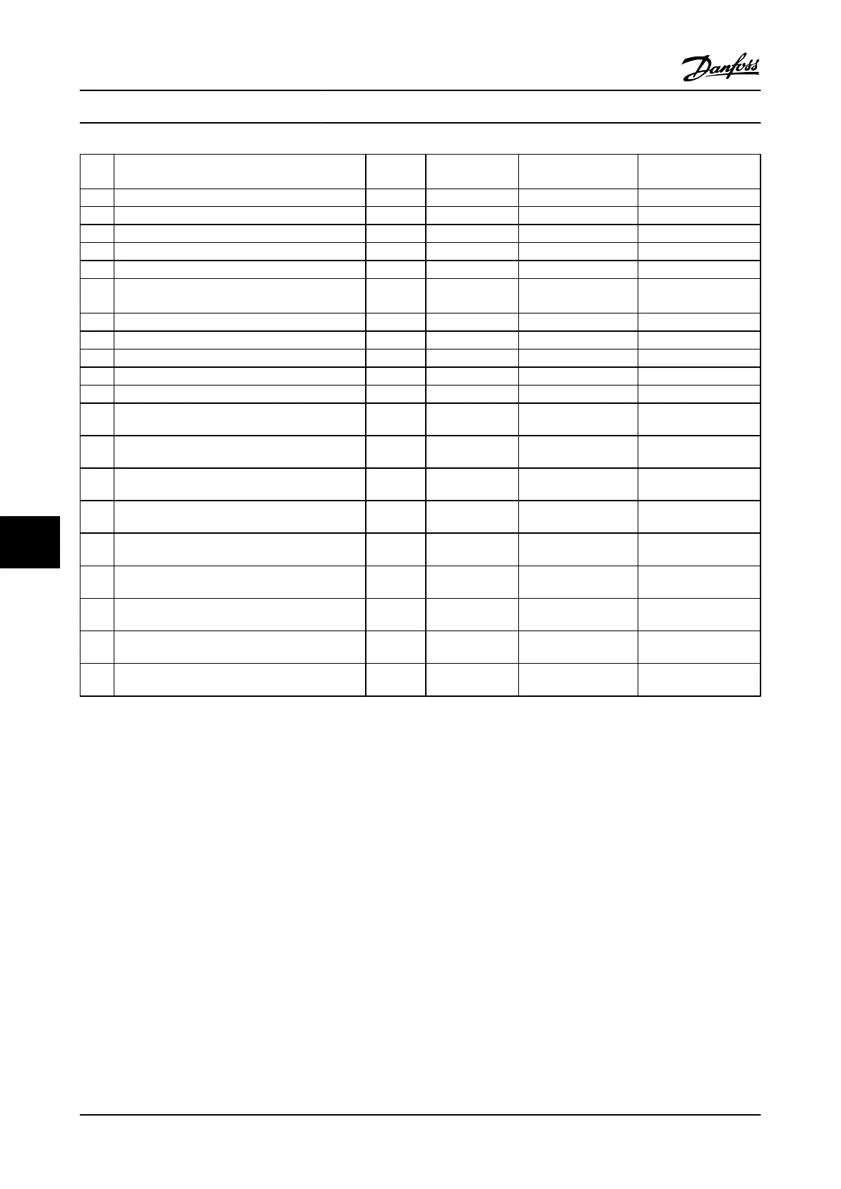
No. Description Warning Alarm/Trip Alarm/Trip Lock Parameter
Reference
82 CSIV parameter error X
83 Illegal Option Combination X
84 No Safety Option X
88 Option Detection X
89 Mechanical Brake Sliding X
90 Feedback Monitor (X) (X) 17-61 Feedback Signal
Monitoring
91 Analog input 54 wrong settings X S202
163 ATEX ETR cur.lim.warning X
164 ATEX ETR cur.lim.alarm X
165 ATEX ETR freq.lim.warning X
166 ATEX ETR freq.lim.alarm X
243 Brake IGBT X X X
244 Heatsink temp X X X
245 Heatsink sensor X X
246 Pwr.card supply X
247 Pwr.card temp X X
248 Illegal PS config X
249 Rect. low temp. X
250 New spare parts X
251 New Type Code X X
Table 8.1 Alarm/Warning Code List
(X) Dependent on parameter
1) Cannot be Auto reset via 14-20 Reset Mode
8.4.1 Fault Messages
The warning/alarm information below defines the warning/
alarm condition, provides the probable cause for the
condition, and details a remedy or troubleshooting
procedure.
WARNING 1, 10V low
The control card voltage is below 10V from terminal 50.
Remove some of the load from terminal 50, as the 10V
supply is overloaded. Max. 15mA or minimum 590 Ω.
This condition can be caused by a short in a connected
potentiometer or improper wiring of the potentiometer.
Troubleshooting
Remove the wiring from terminal 50. If the warning clears,
the problem is with the customer wiring. If the warning
does not clear, replace the control card.
WARNING/ALARM 2, Live zero error
This warning or alarm will only appear if programmed by
the user in 6-01 Live Zero Timeout Function. The signal on
one of the analog inputs is less than 50% of the minimum
value programmed for that input. This condition can be
caused by broken wiring or faulty device sending the
signal.
Troubleshooting
Check connections on all the analog input
terminals. Control card terminals 53 and 54 for
signals, terminal 55 common. MCB 101 terminals
11 and 12 for signals, terminal 10 common. MCB
109 terminals 1, 3, 5 for signals, terminals 2, 4, 6
common).
Check that the Adjustable frequency drive
programming and switch settings match the
analog signal type.
Perform Input Terminal Signal Test.
Warnings and Alarms
VLT
®
AutomationDrive Instruction
Manual
8-4 MG.33.AI.22 - VLT
®
is a registered Danfoss trademark
88

 Loading...


