8.2.6 Closed-loop Control Structure
In closed-loop mode, the drive uses 1 or more references (local or remote) and feedback sensors to control the motor. The
drive receives a feedback signal from a sensor in the system. It then compares this feedback to a setpoint reference value
and determines if there is any discrepancy between these 2 signals. The drive then adjusts the speed of the motor to
correct the discrepancy.
For example, consider a pump application in which the speed of the pump is controlled so that the static pressure in a pipe
is constant (see Illustration 8.7). The drive receives a feedback signal from a sensor in the system. It compares this feedback
to a setpoint reference value and determines the discrepancy if any, between these 2 signals. It then adjusts the speed of
the motor to compensate for the discrepancy.
The static pressure setpoint is the reference signal to the drive. A static pressure sensor measures the actual static pressure
in the pipe and provides this information to the drive as a feedback signal. If the feedback signal exceeds the setpoint
reference, the drive ramps down to reduce the pressure. Similarly, if the pipe pressure is lower than the setpoint reference,
the drive ramps up to increase the pump pressure.
There are 3 types of closed-loop control:
•
Speed control. This type of control requires a speed PID feedback for an input. A properly optimized speed closed-
loop control has higher accuracy than a speed open-loop control.
•
Process control. Used to control application parameters that are measured by
dierent sensors (pressure,
temperature, and ow) and are aected by the connected motor through a pump or fan.
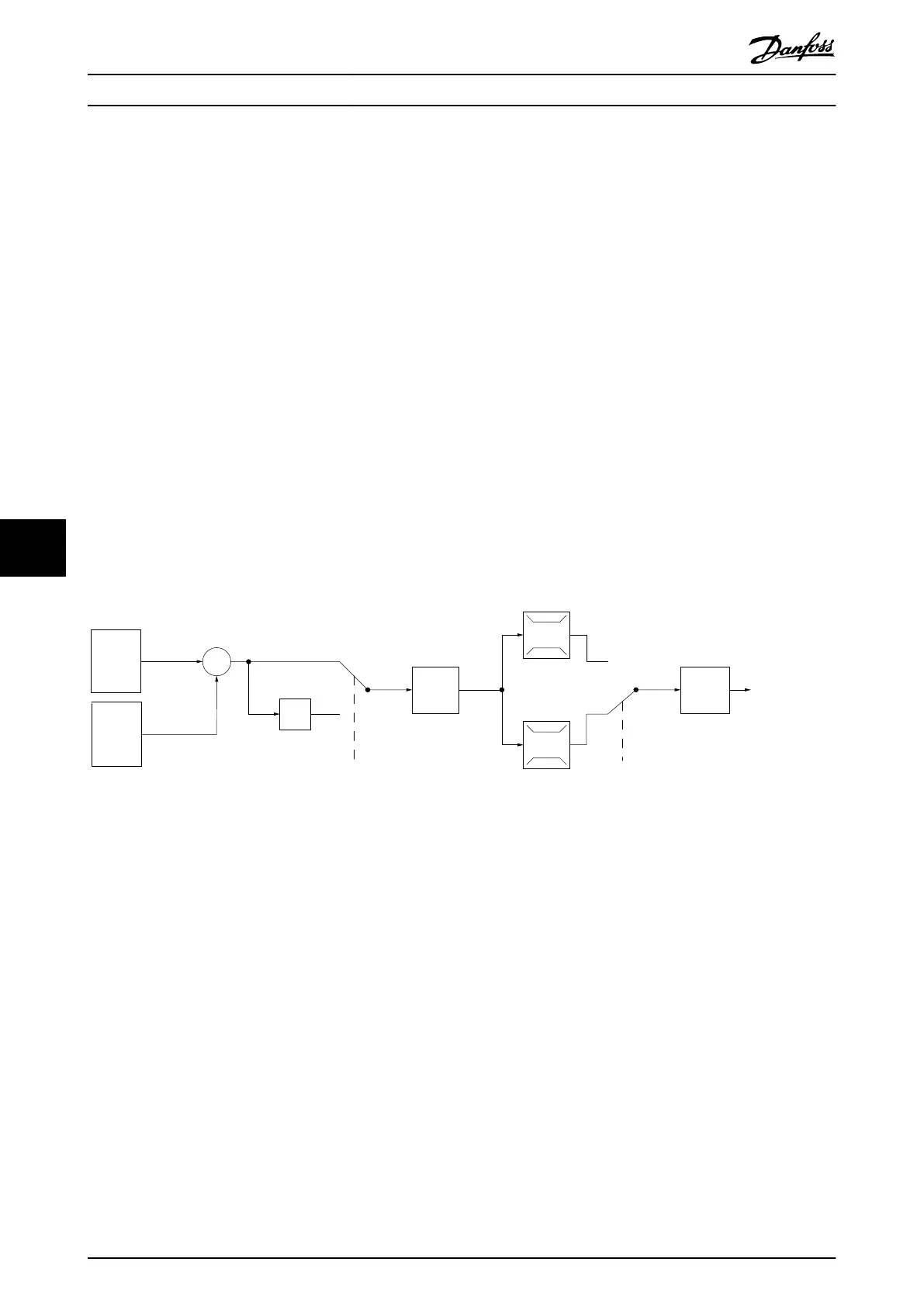
P 20-81
PID Normal/Inverse
Control
PID
Ref.
Handling
Feedback
Handling
Scale to
speed
P 4-10
Motor speed
direction
To motor
control
(Illustra-
tion)
(Illustra-
tion)
130BA359.12
100%
0%
-100%
100%
*[-1]
_
+
Illustration 8.7 Block Diagram of Closed-loop Controller
Programmable features
While the default values for the drive in closed loop often provide satisfactory performance, system control can often be
optimized by tuning the PID parameters. Auto tuning is provided for this optimization.
•
Inverse regulation - motor speed increases when a feedback signal is high.
•
Start-up frequency - lets the system quickly reach an operating status before the PID controller takes over.
•
Built-in lowpass lter - reduces feedback signal noise.
Basic Operating Principles ... VLT® AutomationDrive FC 361
66 Danfoss A/S © 03/2019 All rights reserved. MG06K102
88
 Loading...


