4.3.9 Gland/Conduit Entry - IP21 (NEMA 1) and IP54 (NEMA12)
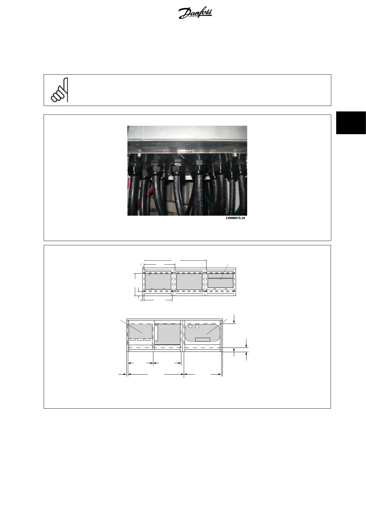
Cables are connected through the gland plate from the bottom. Remove the plate and plan where to place the entry for the glands or conduits. Prepare
holes in the marked area on the drawing.
NB!
The gland plate must be fitted to the frequency converter to ensure the specified protection degree, as well as ensuring proper cooling
of the unit. If the gland plate is not mounted, the frequency converter may trip on Alarm 69, Pwr. Card Temp
Illustration 4.24: Example of proper installation of the gland plate.
Frame size D11
20.0
130BB408.10
420.1
1
2
840.1
55.9
246.0
3x380.0
Frame size E7
130BB418.10
361.7
61.4
420.0380.0
20.0
(1)
1
2
840.0 560.0
(17)(15)
(33) (22)
(14)
(2)
Cable entries viewed from the bottom of the frequency converter
1) Mains cable connection
2) Motor cable connection
VLT HVAC Low Harmonic Drive Operating In-
structions 4 How to Install
MG.16.A1.02 - VLT
®
is a registered Danfoss trademark 37
4
 Loading...


