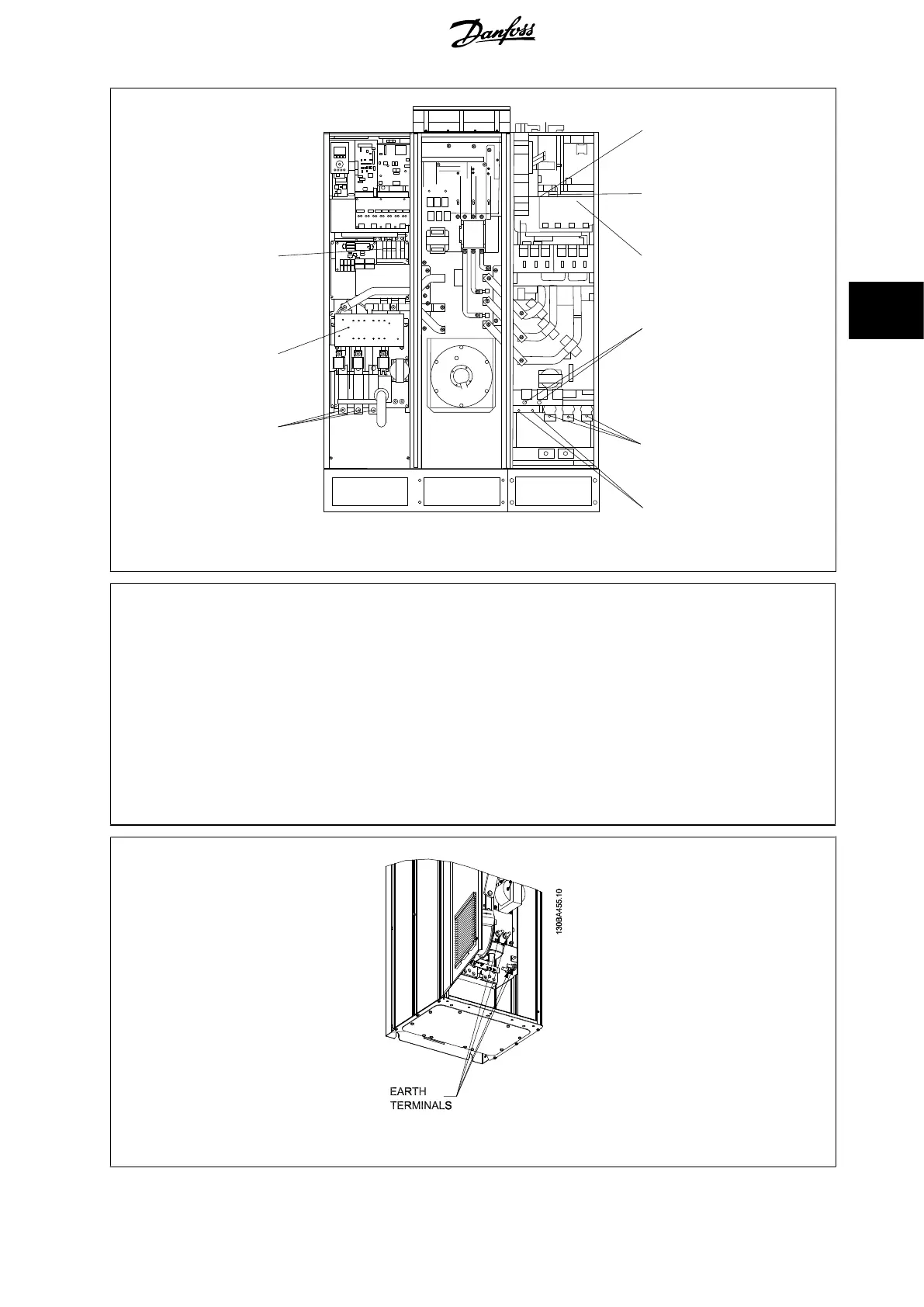
Illustration 4.27: Frame size D11
1) RFI 5) Load sharing option
2) Line -DC +DC
R S T 88 89
L1 L2 L3 6) AUX Fan
3) Brake option 100 101 102 103
-R +R L1 L2 L1 L2
81 82 7) Temp Switch
4) Motor 106 104 105
U V W 8) AUX Relay
96 97 98 01 02 03
T1 T2 T3 04 05 06
9) Fan/ SMPS fuse
Illustration 4.28: Position of earth terminals (drive section)
VLT HVAC Low Harmonic Drive Operating In-
structions
4 How to Install
MG.16.A1.02 - VLT
®
is a registered Danfoss trademark 45
4

 Loading...


