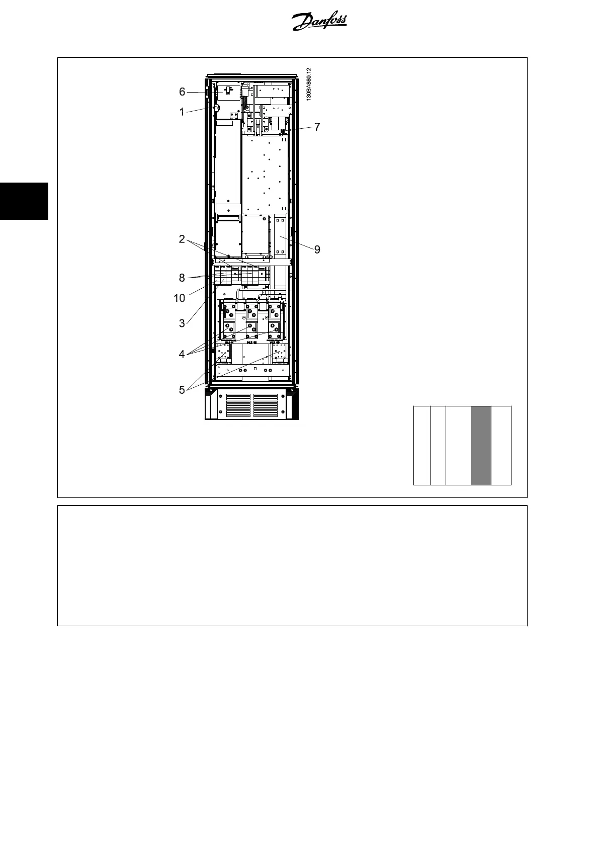
Illustration 4.31: Rectifier Cabinet, frame size F17
Section shown
↓
1) 24 V DC, 5 A 5) Loadsharing
T1 Output Taps -DC +DC
Temp Switch 88 89
106 104 105 6) Control Transformer Fuses (2 or 4 pieces). See fuse tables for part numbers
2) Manual Motor Starters 7) SMPS Fuse. See fuse tables for part numbers
3) 30 A Fuse Protected Power Terminals 8) Manual Motor Controller fuses (3 or 6 pieces). See fuse tables for part numbers
4) Connection point to filter 9) Line Fuses, F1 and F2 frame (3 pieces). See fuse tables for part numbers
R S T 10) 30 Amp Fuse Protected Power fuses
L1 L2 L3
4 How to Install
VLT HVAC Low Harmonic Drive Operating In-
structions
48 MG.16.A1.02 - VLT
®
is a registered Danfoss trademark
4

 Loading...


