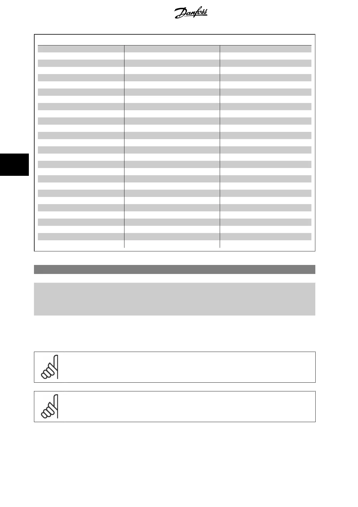
Q3-4 Application Settings
Q3-40 Fan Functions Q3-41 Pump Functions Q3-42 Compressor Functions
Par. 22-60
Broken Belt Function
Par. 22-20
Low Power Auto Set-up
Par. 1-03
Torque Characteristics
Par. 22-61
Broken Belt Torque
Par. 22-21
Low Power Detection
Par. 1-71
Start Delay
Par. 22-62
Broken Belt Delay
Par. 22-22
Low Speed Detection
Par. 22-75
Short Cycle Protection
Par. 4-64
Semi-Auto Bypass Set-up
Par. 22-23
No-Flow Function
Par. 22-76
Interval between Starts
Par. 1-03
Torque Characteristics
Par. 22-24
No-Flow Delay
Par. 22-77
Minimum Run Time
Par. 22-22
Low Speed Detection
Par. 22-40
Minimum Run Time
Par. 5-01
Terminal 27 Mode
Par. 22-23
No-Flow Function
Par. 22-41
Minimum Sleep Time
Par. 5-02
Terminal 29 Mode
Par. 22-24
No-Flow Delay
Par. 22-42
Wake-up Speed [RPM]
Par. 5-12
Terminal 27 Digital Input
Par. 22-40
Minimum Run Time
Par. 22-43
Wake-up Speed [Hz]
Par. 5-13
Terminal 29 Digital Input
Par. 22-41
Minimum Sleep Time
Par. 22-44
Wake-up Ref./FB Difference
Par. 5-40
Function Relay
Par. 22-42
Wake-up Speed [RPM]
Par. 22-45
Setpoint Boost
Par. 1-73
Flying Start
Par. 22-43
Wake-up Speed [Hz]
Par. 22-46
Maximum Boost Time
Par. 1-86
Trip Speed Low [RPM]
Par. 22-44
Wake-up Ref./FB Difference
Par. 22-26
Dry Pump Function
Par. 1-87
Trip Speed Low [Hz]
Par. 22-45
Setpoint Boost
Par. 22-27
Dry Pump Delay
Par. 22-46
Maximum Boost Time
Par. 22-80
Flow Compensation
Par. 2-10
Brake Function
Par. 22-81
Square-linear Curve Approximation
Par. 2-16
AC brake Max. Current
Par. 22-82
Work Point Calculation
Par. 2-17
Over-voltage Control
Par. 22-83
Speed at No-Flow [RPM]
Par. 1-73
Flying Start
Par. 22-84
Speed at No-Flow [Hz]
Par. 1-71
Start Delay
Par. 22-85
Speed at Design Point [RPM]
Par. 1-80
Function at Stop
Par. 22-86
Speed at Design Point [Hz]
Par. 2-00
DC Hold/Preheat Current
Par. 22-87
Pressure at No-Flow Speed
Par. 4-10
Motor Speed Direction
Par. 22-88
Pressure at Rated Speed
Par. 22-89
Flow at Design Point
Par. 22-90
Flow at Rated Speed
Par. 1-03
Torque Characteristics
Par. 1-73
Flying Start
See also
VLT HVAC Drive Programming Guide
for a detailed description of the Function Setups parameter groups.
1-00 Configuration Mode
Option: Function:
[0] * Open Loop Motor speed is determined by applying a speed reference or by setting desired speed when in Hand
Mode.
Open Loop is also used if the frequency converter is part of a closed loop control system based on
an external PID controller providing a speed reference signal as output.
[3] Closed Loop Motor Speed will be determined by a reference from the built-in PID controller varying the motor
speed as part of a closed loop control process (e.g. constant pressure or flow). The PID controller
must be configured in par. 20-** or via the Function Setups accessed by pressing the [Quick Menus]
button.
NB!
This parameter cannot be changed when motor is running.
NB!
When set for Closed Loop, the commands Reversing and Start Reversing will not reverse the direction of the motor.
6 How to Programme the Low Harmonic Drive
VLT HVAC Low Harmonic Drive Operating In-
structions
94 MG.16.A1.02 - VLT
®
is a registered Danfoss trademark
6

 Loading...


