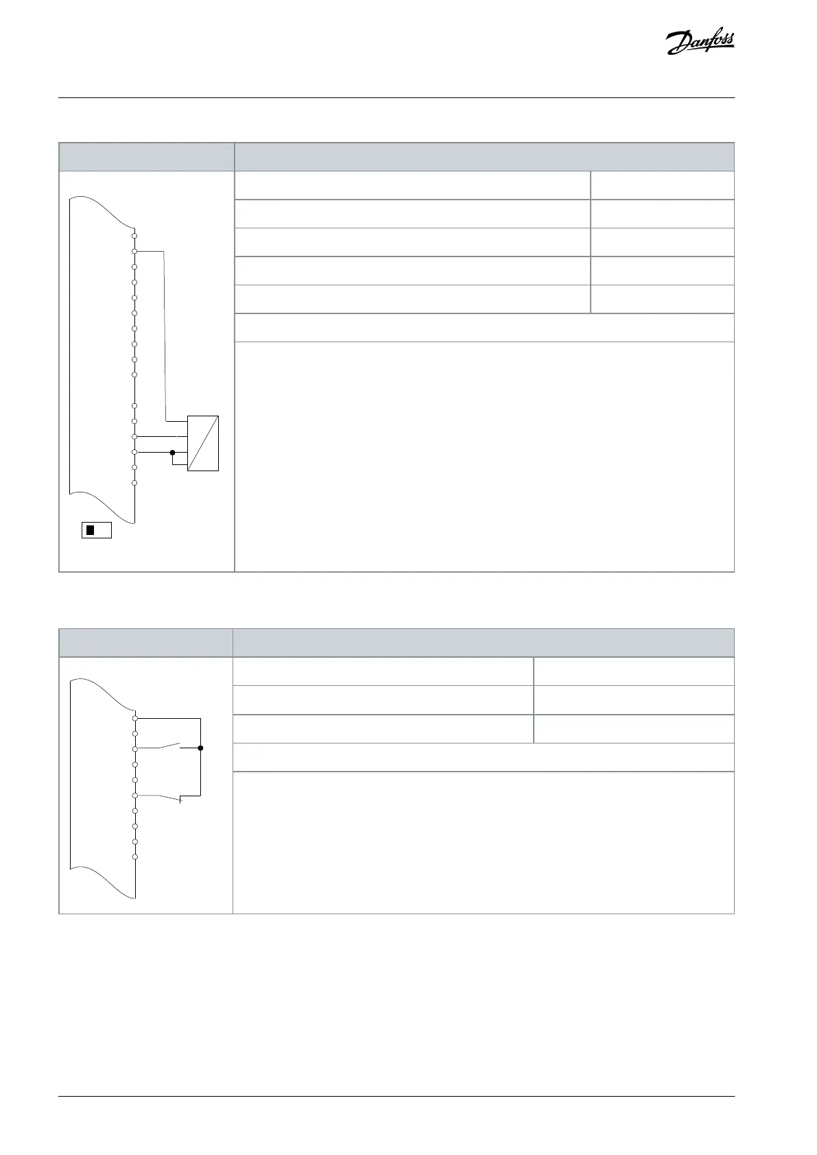
Table 78: Wiring Conguration for Analog Voltage Feedback Transducer (4-wire)
+24 V
+24 V
D IN
D IN
D IN
COM
D IN
D IN
D IN
D IN
+10
0-10 V
+
-
e30bu080.10
XD2.10
XD2.11
XD2.12
XD2.15
XD2.16
XD2.17
XD2.19
XD2.6
Parameter 6-20 Terminal 54 Low Voltage
Parameter 6-21 Terminal 54 High Voltage
Parameter 6-24 Terminal 54 Low Ref./Feedb. value
Parameter 6-25 Terminal 54 High Ref./Feedb. Value
Notes/comments:
D IN 37 is an option.
Terminal 54 in the parameter title corresponds to terminal XD2.8 in the control compartment.
8.1.5 Wiring Conguration: Run/Stop
Table 79: Wiring Conguration for Run/Stop Command with External Interlock
D IN
D IN
D IN
COM
D IN
D IN
D IN
D IN
Parameter 5-10 Terminal 18 Digital Input
Parameter 5-12 Terminal 27 Digital Input
Notes/comments:
D IN 37 is an option.
Terminal 18 in the parameter title corresponds to terminal XD2.12 in the control compartment.
Terminal 27 in the parameter title corresponds to terminal XD2.14 in the control compartment.
AQ357954340588en-000201 / 130R0881108 | Danfoss A/S © 2020.09
Wiring Conguration Examples
VLT® Refrigeration Drive FC 103
Operating Guide
 Loading...


