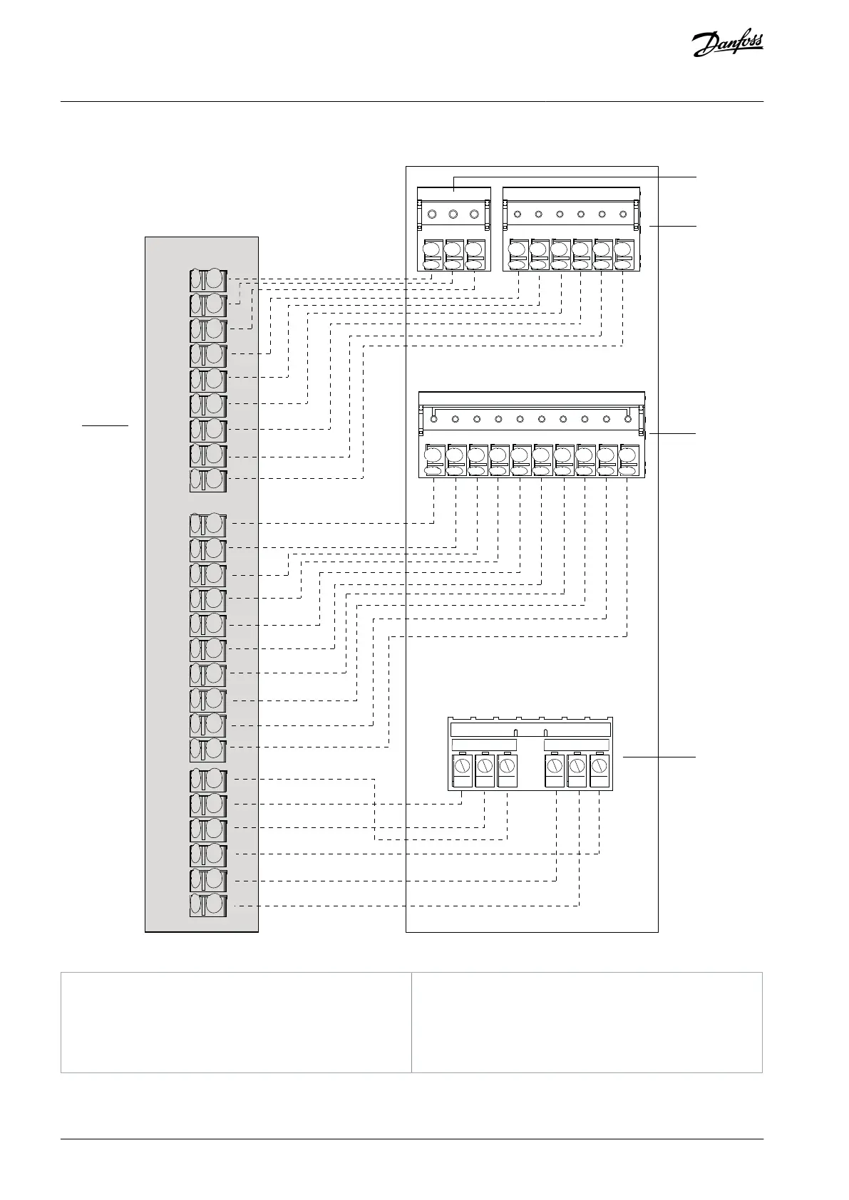
5.5 Control Terminal Wiring Diagram Cross-reference
12 13 18 19 27 29 32 33 20 37
1
26
25
24
23
22
21
R 1 R 2
01 02 03 04 05
06
Illustration 22: Serial Communication, Digital Input/Output, Analog Input/Output, and Relay Terminals Cross-reference
User-accessible terminals (control compartment)
Serial communication terminals (drive module)
Analog input/output terminals (drive module)
Digital input/output terminals (drive module)
Relay terminals (drive module)
AQ357954340588en-000201 / 130R088150 | Danfoss A/S © 2020.09
Electrical Installation
VLT® Refrigeration Drive FC 103
Operating Guide
 Loading...


