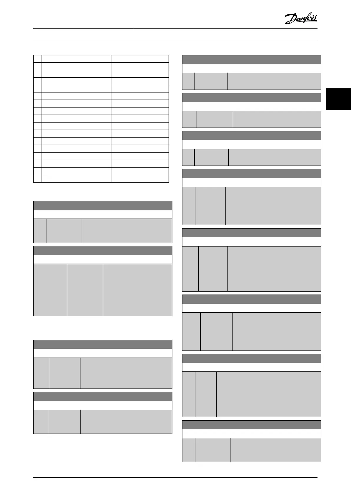
Bit Bit = 0 Bit = 1
00 Control not ready Ready
01 VLT not ready Ready
02 Coasting Enable
03 No fault Trip
04 No warning Warning
05 Reserved –
06 No trip lock Trip lock
07 No warning Warning
08
Speed ≠ ref.
Speed = ref.
09 Local control Bus control
10 Out of range Frequency OK
11 Not running Running
12 No function No function
13 Voltage OK Above limit
14 Current OK Above limit
15 Thermal-level OK Above limit
Table 3.7 Status Word
16-05 Main Actual Value [%]
Range: Function:
0 %* [-200 - 200 %] View the 2 byte word sent with the status
word to the bus master reporting the
main actual value.
16-09 Custom Readout
Range: Function:
0 CustomRea-
doutUnit*
[0 - 9999
CustomRea-
doutUnit]
View the user-dened readouts
as dened in
parameter 0-30 Custom Readout
Unit, parameter 0-31 Custom
Readout Min Value, and
parameter 0-32 Custom Readout
Max Value.
3.12.2 16-1* Motor Status
16-10 Power [kW]
Range: Function:
0 kW* [0 - 1000
kW]
Displays the actual motor power in kW.
The value shown is calculated on the basis
of the actual motor voltage and motor
current.
16-11 Power [hp]
Range: Function:
0 hp* [0 - 1000
hp]
View the actual motor power in hp. The
value shown is calculated based on the
actual motor voltage and motor current.
16-12 Motor Voltage
Range: Function:
0 V* [0 - 65535 V] View the motor voltage, a calculated value
used for controlling the motor.
16-13 Frequency
Range: Function:
0 Hz* [0 - 6553.5 Hz] View the motor frequency, without
resonance damping.
16-14 Motor current
Range: Function:
0 A* [0 - 655.35 A] View the motor current measured as an
average value, I
RMS
.
16-15 Frequency [%]
Range: Function:
0 %* [0 -
6553.5 %]
View a 2-byte word reporting the actual
motor frequency (without resonance
damping) as a percentage (scale 0000–4000
hex) of parameter 4-19 Max Output
Frequency.
16-16 Torque [Nm]
Range: Function:
0 Nm* [-30000 -
30000 Nm]
View the torque value that is applied on
the motor shaft. Some motors supply more
than 160% torque. Consequently, the
minimum value and the maximum value
depend on the minimum/maximum motor
current as well as the motor used.
16-17 Speed [RPM]
Range: Function:
0 RPM* [-30000 -
30000 RPM]
View the actual motor RPM. The motor
RPM is estimated in open-loop process or
closed-loop process control modes and
the motor RPM is measured in speed
closed-loop mode.
16-18 Motor Thermal
Range: Function:
0 %* [0 -
100 %]
View the calculated motor temperature in
percentage of allowed maximum. At 100%, a trip
occurs if selected in parameter 1-90 Motor
Thermal Protection. The basis for the calculation
is the ETR function selected in
parameter 1-90 Motor Thermal Protection.
16-22 Torque [%]
Range: Function:
0 %* [-200 -
200 %]
View the torque in percentage (in relation
to the nominal torque) that is applied to
the motor shaft.
Parameters Programming Guide
MG18B502 Danfoss A/S © 04/2018 All rights reserved. 81
3 3

 Loading...


