•
•
•
Connects the CAM table points with a 5
th
order polynomial. At least 3 consecutive CAM table points of
this type are required to use this selection.
Connects the CAM table points with a full sine wave.
Connects the CAM table points with a full cosine wave.
Always select this option for the last point of the curve.
Parameter 3-39 CAM Follower Gain
Table 221: Parameter 3-39 CAM Follower Gain
Parameter type: Range, 0.0 - 500.0%
Change during operation: True
N O T I C E
This parameter is only available with software version 48.XX.
The follower table is multiplied by this gain which can be adjusted while running.
5.4.5 3-4* Ramp 1
For each of the 4 ramps (parameter groups 3-4* Ramp 1, 3-5* Ramp 2, 3-6* Ramp 3, and 3-7* Ramp 4) configure the ramp parameters:
Ramp type
Ramping times (duration of acceleration and deceleration)
Level of jerk compensation for S-ramps
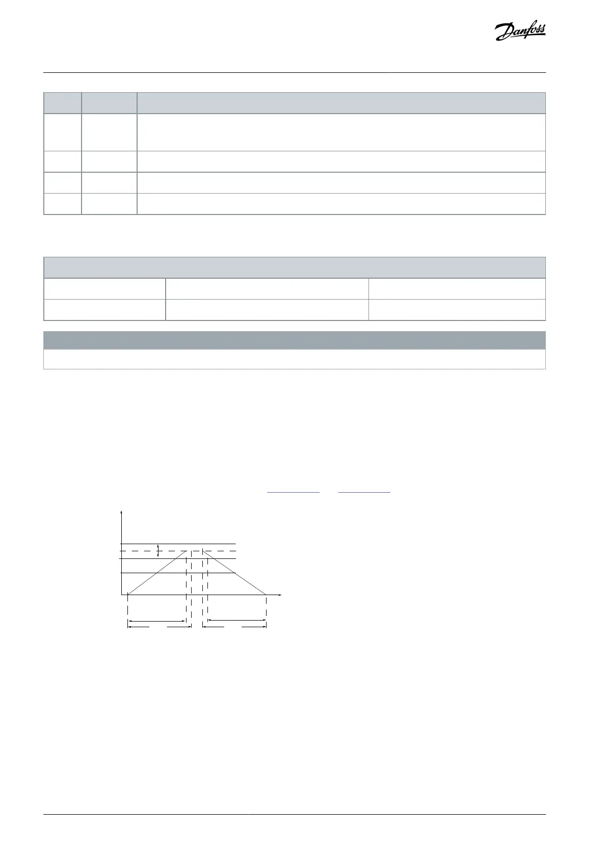
Start by setting the linear ramping times corresponding to
Illustration 51 and Illustration 52.
P 3-*2
Ramp (X) Down
Time (Dec)
P 4-13
High-limit
Time
P 3-*1
Ramp (X)Up
Time (Acc)
t
Illustration 51: Linear Ramping Times
If S-ramps are selected, set the level of non-linear jerk compensation required. Set jerk compensation by defining the proportion of
ramp-up and ramp-down times where acceleration and deceleration are variable (that is, increasing or decreasing). The S-ramp ac-
celeration and deceleration settings are defined as a percentage of the actual ramp time.
AU275636650261en-000101 / 130R0334142 | Danfoss A/S © 2022.12
Parameter Descriptions
VLT AutomationDrive FC 301/302
Programming Guide

 Loading...


